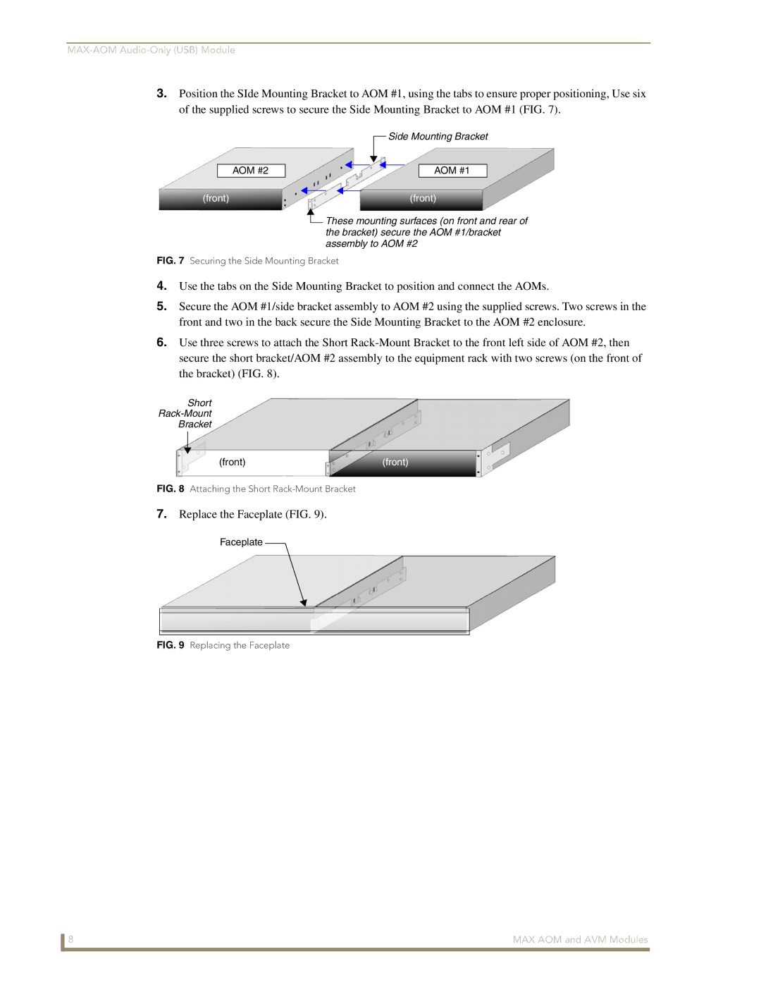
3.Position the SIde Mounting Bracket to AOM #1, using the tabs to ensure proper positioning, Use six of the supplied screws to secure the Side Mounting Bracket to AOM #1 (FIG. 7).
AOM #2
![]() Side Mounting Bracket
Side Mounting Bracket
AOM #1
(front) | (front) |
![]() These mounting surfaces (on front and rear of the bracket) secure the AOM #1/bracket assembly to AOM #2
These mounting surfaces (on front and rear of the bracket) secure the AOM #1/bracket assembly to AOM #2
FIG. 7 Securing the Side Mounting Bracket
4.Use the tabs on the Side Mounting Bracket to position and connect the AOMs.
5.Secure the AOM #1/side bracket assembly to AOM #2 using the supplied screws. Two screws in the front and two in the back secure the Side Mounting Bracket to the AOM #2 enclosure.
6.Use three screws to attach the Short
Short
Bracket
(front) | (front) |
FIG. 8 Attaching the Short Rack-Mount Bracket
7.Replace the Faceplate (FIG. 9).
Faceplate
FIG. 9 Replacing the Faceplate
8 | MAX AOM and AVM Modules |