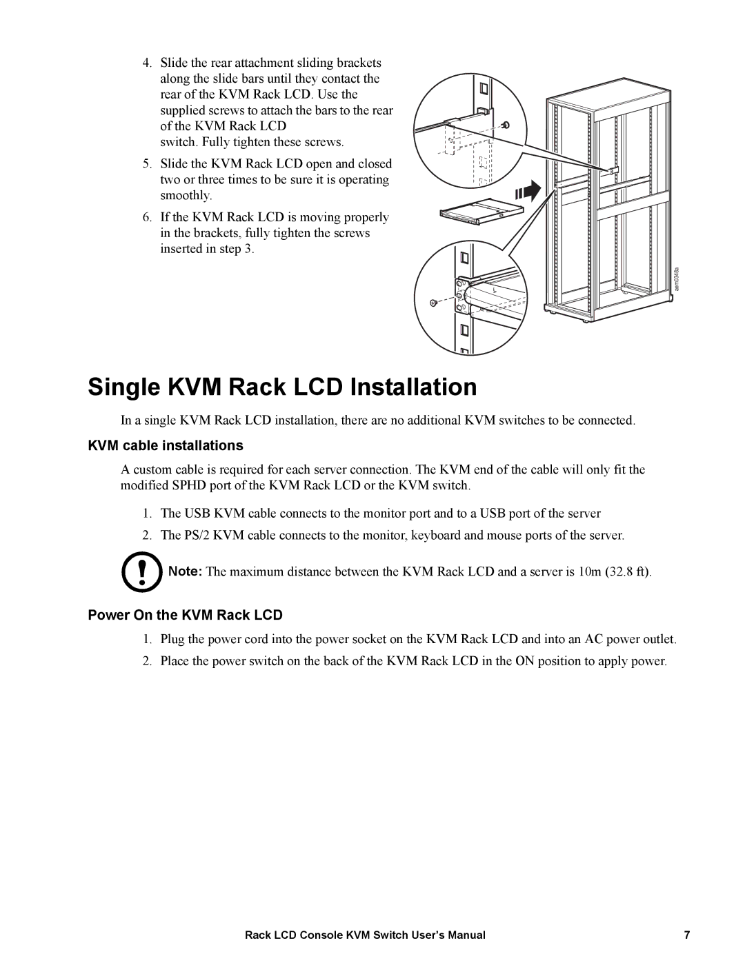
4.Slide the rear attachment sliding brackets along the slide bars until they contact the
rear of the KVM Rack LCD. Use the supplied screws to attach the bars to the rear of the KVM Rack LCD
switch. Fully tighten these screws.
5. Slide the KVM Rack LCD open and closed two or three times to be sure it is operating smoothly.
6. If the KVM Rack LCD is moving properly in the brackets, fully tighten the screws inserted in step 3.
aem0348a
Single KVM Rack LCD Installation
In a single KVM Rack LCD installation, there are no additional KVM switches to be connected.
KVM cable installations
A custom cable is required for each server connection. The KVM end of the cable will only fit the modified SPHD port of the KVM Rack LCD or the KVM switch.
1.The USB KVM cable connects to the monitor port and to a USB port of the server
2.The PS/2 KVM cable connects to the monitor, keyboard and mouse ports of the server.
Note: The maximum distance between the KVM Rack LCD and a server is 10m (32.8 ft).
Power On the KVM Rack LCD
1.Plug the power cord into the power socket on the KVM Rack LCD and into an AC power outlet.
2.Place the power switch on the back of the KVM Rack LCD in the ON position to apply power.
Rack LCD Console KVM Switch User’s Manual | 7 |