Installation

Power & Reset options

The thermostat is dual power.. It can either be AC or battery powered, or both (to provide backup power for the clock). Batteries are optional if your thermostat was wired to run on AC power when installed..

RESET

BUTTON

Installation

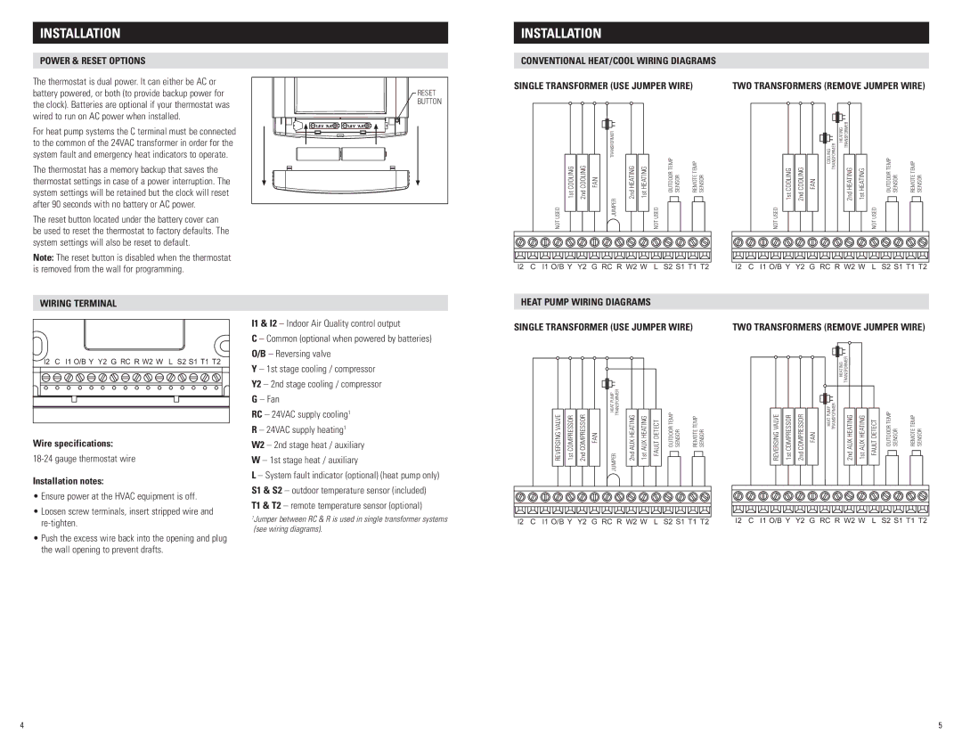
CONVENTIONAL HEAT/COOL WIRING DIAGRAMS

Single transformer (use Jumper wire)

Two transformers (Remove Jumper Wire)


For heat pump systems the C terminal must be connected to the common of the 24VAC transformer in order for the system fault and emergency heat indicators to operate..

The thermostat has a memory backup that saves the thermostat settings in case of a power interruption.. The system settings will be retained but the clock will reset after 90 seconds with no battery or AC power..

The reset button located under the battery cover can be used to reset the thermostat to factory defaults.. The system settings will also be reset to default..

NOT USED

COOLING

COOLING

FAN

1st

2nd


JUMPERTRANSFORMER

2nd HEATING 1st HEATING

OUTDOOR TEMP SENSOR

REMOTE TEMP SENSOR

NOT USED

NOT USED

COOLING

COOLING

FAN

1st

2nd


COOLING TRANSFORMER

TRANSFORMER

HEATING

2nd HEATING 1st HEATING

OUTDOOR TEMP SENSOR

REMOTE TEMP SENSOR

NOT USED

Note: The reset button is disabled when the thermostat is removed from the wall for programming..

I2 C I1 O/B Y Y2 G RC R W2 W L S2 S1 T1 T2

I2 C I1 O/B Y Y2 G RC R W2 W L S2 S1 T1 T2

Wiring terminal

I1 & I2 – Indoor Air Quality control output

HEAT PUMP WIRING DIAGRAMS

Single transformer (use Jumper wire)

Two transformers (Remove Jumper Wire)

Wire specifications:

18-24 gauge thermostat wire

Installation notes:

• Ensure power at the HVAC equipment is off.

• Loosen screw terminals, insert stripped wire and

C – Common (optional when powered by batteries) O/B – Reversing valve

Y – 1st stage cooling / compressor

Y2 – 2nd stage cooling / compressor G – Fan

RC – 24VAC supply cooling1 R – 24VAC supply heating1

W2 – 2nd stage heat / auxiliary

W – 1st stage heat / auxiliary

L – System fault indicator (optional) (heat pump only) S1 & S2 – outdoor temperature sensor (included)

T1 & T2 – remote temperature sensor (optional)

REVERSING VALVE 1st COMPRESSOR 2nd COMPRESSOR FAN

JUMPERTRANSFORMERHEAT PUMP

2nd AUX HEATING 1st AUX HEATING FAULT DETECT

OUTDOOR TEMP SENSOR

REMOTE TEMP SENSOR


REVERSING VALVE


COMPRESSOR

COMPRESSOR

FAN


1st

2nd


HEATING TRANSFORMER


HEAT PUMP TRANSFORMER


2nd AUX HEATING

1st AUX HEATING

FAULT DETECT


OUTDOOR TEMP SENSOR

REMOTE TEMP SENSOR


re-tighten..

• Push the excess wire back into the opening and plug

the wall opening to prevent drafts..

1Jumper between RC & R is used in single transformer systems (see wiring diagrams).

I2 C I1 O/B Y Y2 G RC R W2 W L S2 S1 T1 T2

I2 C I1 O/B Y Y2 G RC R W2 W L S2 S1 T1 T2

4

5

Page 3
Image 3
Aprilaire 8620 installation instructions Conventional HEAT/COOL Wiring Diagrams, Heat Pump Wiring Diagrams

8620 specifications

The Aprilaire 8620 is a cutting-edge thermostat designed to enhance home comfort while promoting energy efficiency. This advanced device combines innovative features and smart technology, making it an ideal choice for homeowners seeking to optimize their HVAC systems.

One of the standout features of the Aprilaire 8620 is its user-friendly interface. The thermostat boasts a large, easy-to-read display that allows users to quickly navigate through its settings. This intuitive design ensures that adjusting temperature settings or changing modes is a hassle-free experience. The backlit screen is especially beneficial in low-light situations, providing visibility for users at any time of day.

The Aprilaire 8620 is equipped with a programmable scheduling feature that enables users to create tailored heating and cooling schedules. This functionality allows homeowners to set specific temperatures for different times of the day, ensuring maximum comfort when they are home while minimizing energy use when away. The advanced programming capability promotes energy savings by automatically adjusting the temperature settings based on user preferences and daily routines.

Furthermore, the thermostat incorporates Wi-Fi connectivity, allowing for remote access through a smartphone application. This feature enables users to monitor and adjust their home’s temperature from anywhere, providing ultimate control and flexibility. Notifications and alerts can also be sent to the user’s mobile device, ensuring they are always informed about their HVAC system's performance.

Another key characteristic of the Aprilaire 8620 is its compatibility with multiple heating and cooling systems. Whether a home utilizes a single-stage or multi-stage system, the thermostat can seamlessly integrate, providing a versatile solution for various HVAC setups. This compatibility ensures that users can make the most of their existing equipment without costly upgrades.

Additionally, the thermostat offers advanced humidity control features, which work in conjunction with Aprilaire's whole-home humidifiers and dehumidifiers. This technology not only improves overall indoor air quality but also enhances comfort levels by managing humidity effectively, preventing issues like mold growth and allergens.

In summary, the Aprilaire 8620 stands out as a premium thermostat option that combines user-friendly design, programmable scheduling, Wi-Fi connectivity, compatibility with multiple systems, and advanced humidity control. With its suite of features and smart technology, it represents a significant investment in home comfort and energy efficiency for any homeowner.