Defiant 1610
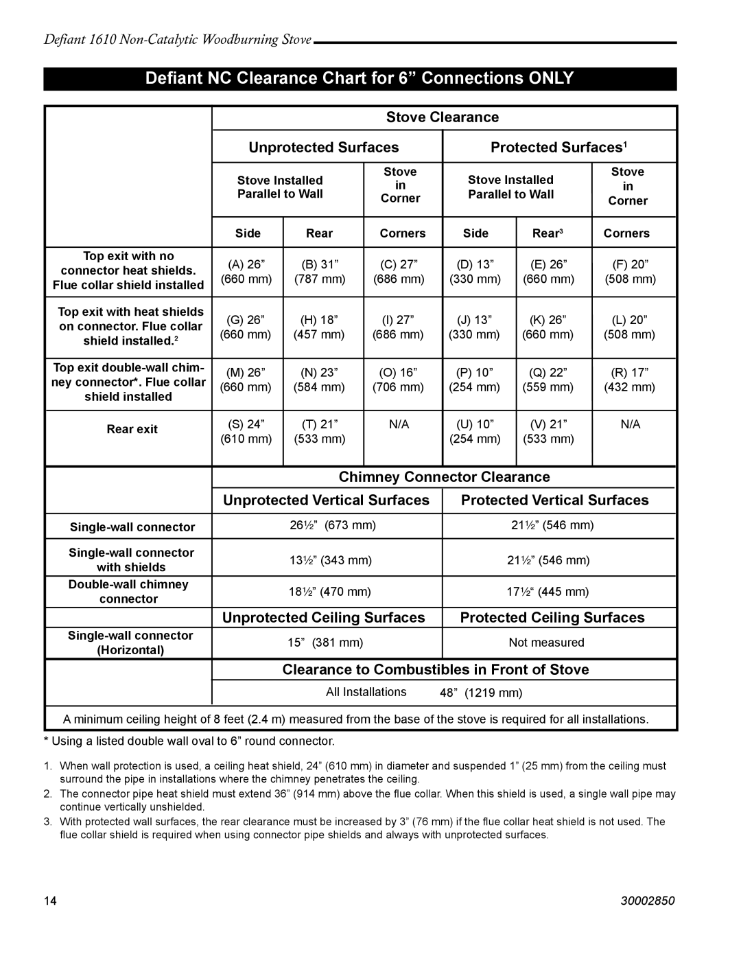
Defiant NC Clearance Chart for 6” Connections ONLY
|
|
|
|
|
| Stove Clearance |
|
|
|
|
| ||
|
|
|
|
|
|
|
|
|
|
| |||
|
|
| Unprotected Surfaces |
| Protected Surfaces1 | ||||||||
|
|
|
|
|
|
|
|
|
|
|
|
| |
|
|
| Stove Installed |
| Stove |
| Stove Installed | Stove | |||||
|
|
|
| in |
| in | |||||||
|
|
| Parallel to Wall |
|
| Parallel to Wall | |||||||
|
|
|
| Corner |
| Corner | |||||||
|
|
|
|
|
|
|
|
|
| ||||
|
|
|
|
|
|
|
|
|
|
|
|
|
|
|
|
| Side | Rear |
| Corners |
| Side |
| Rear3 | Corners | ||
|
|
|
|
|
|
|
|
|
|
|
|
|
|
| Top exit with no | (A) 26” | (B) 31” |
| (C) 27” |
| (D) 13” |
| (E) 26” | (F) 20” | |||
| connector heat shields. |
|
|
| |||||||||
| (660 mm) | (787 mm) |
| (686 mm) |
| (330 mm) |
| (660 mm) | (508 mm) | ||||
| Flue collar shield installed |
|
|
| |||||||||
|
|
|
|
|
|
|
|
|
|
|
| ||
|
|
|
|
|
|
|
|
|
|
|
|
| |
| Top exit with heat shields | (G) 26” | (H) 18” |
| (I) 27” |
| (J) 13” |
| (K) 26” | (L) 20” | |||
| on connector. Flue collar |
|
|
| |||||||||
| (660 mm) | (457 mm) |
| (686 mm) |
| (330 mm) |
| (660 mm) | (508 mm) | ||||
| shield installed.2 |
|
|
| |||||||||
|
|
|
|
|
|
|
|
|
|
|
|
| |
| Top exit | (M) 26” | (N) 23” |
| (O) 16” |
| (P) 10” |
| (Q) 22” | (R) 17” | |||
| ney connector*. Flue collar |
|
|
| |||||||||
| (660 mm) | (584 mm) |
| (706 mm) |
| (254 mm) |
| (559 mm) | (432 mm) | ||||
| shield installed |
|
|
| |||||||||
|
|
|
|
|
|
|
|
|
|
|
| ||
|
|
|
|
|
|
|
|
|
|
|
| ||
| Rear exit | (S) 24” | (T) 21” |
| N/A |
| (U) 10” |
| (V) 21” | N/A | |||
| (610 mm) | (533 mm) |
|
|
| (254 mm) |
| (533 mm) |
|
|
| ||
|
|
|
|
|
|
|
|
|
| ||||
|
|
|
|
|
|
|
|
|
|
| |||
|
|
|
| Chimney Connector Clearance |
|
|
| ||||||
|
|
|
|
|
|
|
|
|
| ||||
|
|
| Unprotected Vertical Surfaces |
| Protected Vertical Surfaces | ||||||||
|
|
|
|
|
|
|
|
|
|
| |||
|
| 26¹⁄₂” (673 mm) |
|
| 21¹⁄₂” (546 mm) |
|
|
| |||||
|
|
|
|
|
|
|
|
|
|
|
|
|
|
|
| 13¹⁄₂” (343 mm) |
|
|
| 21¹⁄₂” (546 mm) |
|
|
| ||||
| with shields |
|
|
|
|
|
|
| |||||
|
|
|
|
|
|
|
|
|
|
|
| ||
|
|
|
|
|
|
|
|
|
|
|
|
| |
|
| 18¹⁄₂” (470 mm) |
|
|
| 17¹⁄₂“ (445 mm) |
|
|
| ||||
| connector |
|
|
|
|
|
|
| |||||
|
|
|
|
|
|
|
|
|
|
|
| ||
|
|
| Unprotected Ceiling Surfaces |
| Protected Ceiling Surfaces | ||||||||
|
| 15” (381 mm) |
|
|
| Not measured |
|
|
| ||||
| (Horizontal) |
|
|
|
|
|
|
| |||||
|
|
|
|
|
|
|
|
|
|
|
| ||
|
|
|
| Clearance to Combustibles in Front of Stove |
|
|
| ||||||
|
|
|
|
|
|
|
|
| |||||
|
|
|
| All Installations | 48” (1219 mm) |
|
|
| |||||
|
|
|
|
|
|
|
|
|
|
|
|
|
|
A minimum ceiling height of 8 feet (2.4 m) measured from the base of the stove is required for all installations.
* Using a listed double wall oval to 6” round connector.
1.When wall protection is used, a ceiling heat shield, 24” (610 mm) in diameter and suspended 1” (25 mm) from the ceiling must surround the pipe in installations where the chimney penetrates the ceiling.
2.The connector pipe heat shield must extend 36” (914 mm) above the flue collar. When this shield is used, a single wall pipe may continue vertically unshielded.
3.With protected wall surfaces, the rear clearance must be increased by 3” (76 mm) if the flue collar heat shield is not used. The flue collar shield is required when using connector pipe shields and always with unprotected surfaces.
14 | 30002850 |