Defiant 1610
Fan Kit Installation
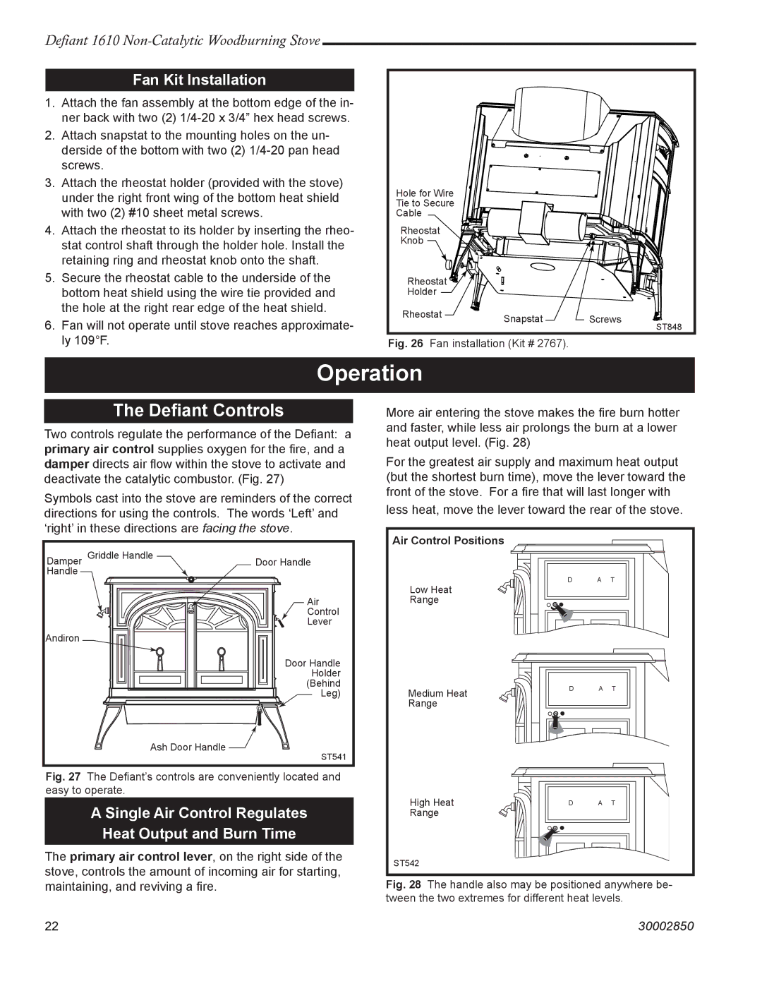
1.Attach the fan assembly at the bottom edge of the in- ner back with two (2)
2.Attach snapstat to the mounting holes on the un- derside of the bottom with two (2)
3.Attach the rheostat holder (provided with the stove) under the right front wing of the bottom heat shield with two (2) #10 sheet metal screws.
4.Attach the rheostat to its holder by inserting the rheo- stat control shaft through the holder hole. Install the retaining ring and rheostat knob onto the shaft.
5.Secure the rheostat cable to the underside of the bottom heat shield using the wire tie provided and the hole at the right rear edge of the heat shield.
6.Fan will not operate until stove reaches approximate- ly 109°F.
Hole for Wire
Tie to Secure
Cable
Rheostat
Knob
Rheostat ![]()
![]()
![]()
![]()
Holder
Rheostat | Snapstat | Screws |
| ||
|
| ST848 |
Fig. 26 Fan installation (Kit # 2767).
Operation
The Defiant Controls
Two controls regulate the performance of the Defiant: a primary air control supplies oxygen for the fire, and a damper directs air flow within the stove to activate and deactivate the catalytic combustor. (Fig. 27)
Symbols cast into the stove are reminders of the correct directions for using the controls. The words ‘Left’ and ‘right’ in these directions are facing the stove.
Damper Griddle Handle | Door Handle | ||||
Handle |
|
|
| ||
|
|
|
|
|
|
Air
Control
Lever
Andiron
Door Handle Holder (Behind Leg)
Ash Door Handle ![]()
ST541
Fig. 27 The Defiant’s controls are conveniently located and easy to operate.
A Single Air Control Regulates
Heat Output and Burn Time
The primary air control lever, on the right side of the stove, controls the amount of incoming air for starting, maintaining, and reviving a fire.
More air entering the stove makes the fire burn hotter and faster, while less air prolongs the burn at a lower heat output level. (Fig. 28)
For the greatest air supply and maximum heat output (but the shortest burn time), move the lever toward the front of the stove. For a fire that will last longer with
less heat, move the lever toward the rear of the stove.
Air Control Positions
D E F I A N T
� � � � � � �
Low Heat
Range
| D E F I A N T |
Medium Heat | � � � � � � � |
Range |
|
High Heat | � � � � � � � |
| D E F I A N T |
Range |
|
ST542
Fig. 28 The handle also may be positioned anywhere be- tween the two extremes for different heat levels.
22 | 30002850 |