Defiant 1610
Defiant NC Clearance Chart for 8” Connections ONLY
|
|
|
|
| Stove Clearance1 |
|
|
|
| ||
|
|
|
|
|
|
|
|
| |||
|
| Unprotected Surfaces |
| Protected Surfaces | |||||||
|
|
|
|
|
|
|
|
|
|
|
|
|
| Stove Installed |
| Stove |
| Stove Installed | Stove | ||||
|
|
| in |
| in | ||||||
|
| Parallel to Wall |
|
| Parallel to Wall | ||||||
|
|
| Corner |
| Corner | ||||||
|
|
|
|
|
|
|
|
| |||
|
|
|
|
|
|
|
|
|
|
|
|
|
| Side | Rear |
| Corners |
| Side |
| Rear2 | Corners | |
|
|
|
|
|
|
|
|
|
|
|
|
Top exit with no | (A) 24”3 | (B) 35”3 |
| (C) 25”3 |
| (D) 11” |
| (E) 15” | (F) 9” | ||
connector heat shields. |
|
|
| ||||||||
(610 mm) | (889 mm) |
| (635 mm) |
| (279 mm) |
| (381 mm) | (229 mm) | |||
Flue collar shield installed |
|
|
| ||||||||
|
|
|
|
|
|
|
|
|
| ||
|
|
|
|
|
|
|
|
|
|
| |
Top exit with heat shields | (G) 26”4 | (H) 17”4 |
| (I) 25”4 |
| (J) 11” |
| (K) 15” | (L) 9” | ||
on connector. Flue collar |
|
|
| ||||||||
(660 mm) | (430 mm) |
| (635 mm) |
| (279 mm) |
| (381 mm) | (229 mm) | |||
shield installed |
|
|
| ||||||||
|
|
|
|
|
|
|
|
|
| ||
|
|
|
|
|
|
|
|
|
|
| |
Top exit | (M) 25” | (N) 22” |
| (O) 14” |
| (P) 8” |
| (Q) 11” | (R) 6” | ||
chimney connector*. Flue |
|
|
| ||||||||
(635 mm) | (559 mm) |
| (356 mm) |
| (203 mm) |
| (279 mm) | (152 mm) | |||
collar shield installed |
|
|
| ||||||||
|
|
|
|
|
|
|
|
|
| ||
|
|
|
|
|
|
|
|
|
|
| |
Rear exit | (S) 21” | (T) 21” |
| N/A |
| (U) 8” |
| (V) 21” | N/A | ||
(533 mm) | (533 mm) |
|
|
| (203 mm) |
| (533 mm) |
|
| ||
|
|
|
|
|
|
|
| ||||
|
|
|
|
|
|
|
|
| |||
|
|
| Chimney Connector Clearance |
|
| ||||||
|
|
|
|
|
|
|
|
| |||
|
| Unprotected Vertical Surfaces |
| Protected Vertical Surfaces | |||||||
|
|
|
|
|
|
|
|
| |||
| 29¹⁄₂” (749 mm) |
|
| 9¹⁄₂” (241 mm) |
|
| |||||
|
|
|
|
|
|
|
|
|
|
|
|
| 11¹⁄₂” (292 mm) |
|
|
| 9¹⁄₂” (241 mm) |
|
| ||||
with shields |
|
|
|
|
|
| |||||
|
|
|
|
|
|
|
|
|
| ||
| 16¹⁄₂” (419 mm) |
|
|
| 5¹⁄₂” (140 mm) |
|
| ||||
connector |
|
|
|
|
|
| |||||
|
|
|
|
|
|
|
|
|
| ||
|
| Unprotected Ceiling Surfaces |
| Protected Ceiling Surfaces | |||||||
|
|
|
|
|
|
|
|
|
|
| |
| 30” (762 mm) |
|
|
| 19” (483 mm) |
|
| ||||
(Horizontal) |
|
|
|
|
|
| |||||
|
|
|
|
|
|
|
|
|
| ||
|
|
|
|
|
|
| |||||
|
|
| Clearance to Combustibles in Front of Stove |
|
| ||||||
|
|
|
|
|
|
| |||||
|
|
| All Installations | 48” (1219 mm) |
|
| |||||
|
|
|
|
|
|
|
| ||||
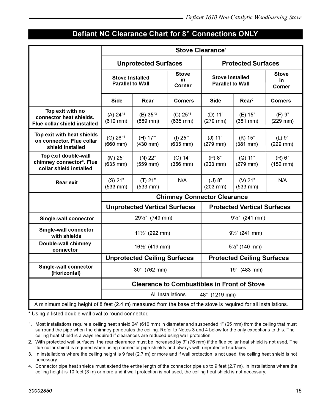
A minimum ceiling height of 8 feet (2.4 m) measured from the base of the stove is required for all installations. | |||||||||||
|
|
|
|
|
|
|
|
|
|
|
|
* Using a listed double wall oval to round connector. |
|
|
|
|
|
|
| ||||
1.Most installations require a ceiling heat shield 24” (610 mm) in diameter and suspended 1” (25 mm) from the ceiling that must surround the pipe when the chimney penetrates the ceiling. Refer to Notes 3 and 4 below for the only exceptions to this. The ceiling heat shield is always required if clearances are reduced using wall protection.
2.With protected wall surfaces, the rear clearance must be increased by 3” (76 mm) if the flue collar heat shield is not used. The flue collar shield is required when using connector pipe shields and always with unprotected surfaces.
3.In installations where the ceiling height is 9 feet (2.7 m) or more and if wall protection is not used, the ceiling heat shield is not necessary.
4.Connector pipe heat shields must extend the entire length of the connector pipe up to 9 feet (2.7 m). In installations where the ceiling height is 10 feet (3 m) or more and if wall protection is not used, the ceiling heat shield is not necessary.
30002850 | 15 |
