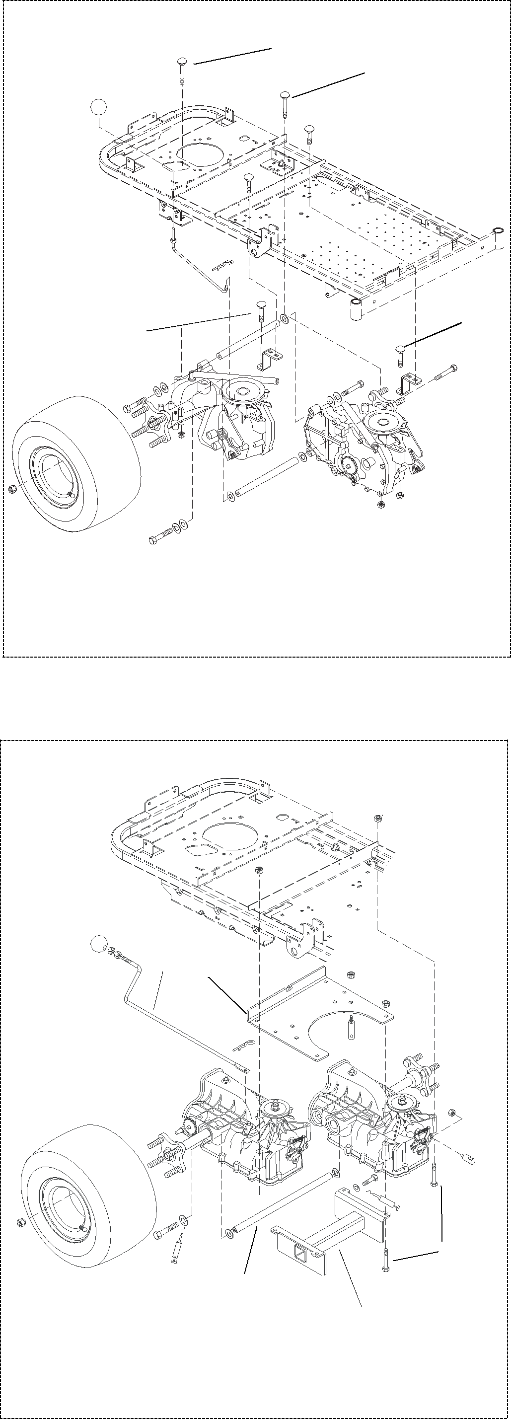
Model EZT 915065, 502
 2
2
 2
2
1
2
2 
1. Dump Rod
2. Anchor Bolts
PE0260
Figure 20
Model IZT 915055, 057, 059, 067, 501
1 3
|
|
| 2 |
|
| 4 |
|
|
|
| 5 |
1. | Dump Rod | 4. | Axle Brace Rod |
2. | Anchor Bolts | 5. | Axle Brace |
3. | Axle Support Bracket |
| Weldment |
Figure 21
7.2HYDRO-GEAR FLUID RECOMMENDATIONS
The fluids used in
Typically, an engine oil with a minimum rating of 55 sus at 210oF and an API classification of SH/CD is recommended. A
7.3HYDRO-GEAR TRANSMISSION REMOVAL
1.Place the unit on a flat surface and remove the negative lead from the battery and the spark plug lead from the spark plug.
2.Remove key and spark plug wire.
3.Raise and block the unit frame on jack stands behind the transaxle in the frame.
4.Remove the rear wheels by removing the lug nuts holding the wheels to the axle hub.
5.Release the transmission belt tension spring and remove the transmission belt from the input sheave on top of the transaxles.
6.Release the parking brake.
7.At the end of each brace rod (Figure 21) remove the hairpin and pull the rods away from the transmission.
8.At the end of each steering link, (Figure 20 and Figure 21) remove the hairpin and pull the links away from the transmission.
9.Remove the dump rod from the transmission.
10.Do not remove or loosen the hardware on the transaxle
11.Support the transaxles with a floor jack from the rear of the tractor.
12.Remove the two right and left front anchor bolts holding the transaxle to the tractor frame and remove the two rear anchor bolts from the left and right side holding the transaxle to the units frame and lower jack.
13.With the transaxle assembly removed from the units frame, place the axle assembly on a flat work surface.
7 - 22