2.4 Installation of CPU Fan and Heatsink
This motherboard is equipped with
For proper installation, please kindly refer to the instruction manuals of your CPU fan and heatsink.
Below is an example to illustrate the installation of the heatsink for
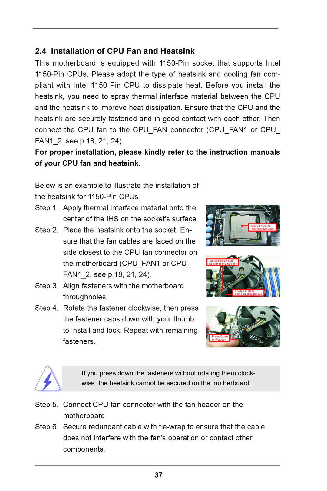
Step 1. Apply thermal interface material onto the center of the IHS on the socket’s surface.
Step 2. Place the heatsink onto the socket. En- sure that the fan cables are faced on the side closest to the CPU fan connector on the motherboard (CPU_FAN1 or CPU_ FAN1_2, see p.18, 21, 24).
Step 3. Align fasteners with the motherboard throughholes.
Step 4. Rotate the fastener clockwise, then press the fastener caps down with your thumb to install and lock. Repeat with remaining fasteners.
Apply Thermal
Interface Material
Fan cables on side closest to MB header
Fastener slots pointing straight out
Press Down
(4 Places)
If you press down the fasteners without rotating them clock- wise, the heatsink cannot be secured on the motherboard.
Step 5. Connect CPU fan connector with the fan header on the motherboard.
Step 6. Secure redundant cable with
37