Connect the power switch, reset switch and system status indica- tor on the chassis to this header according to the pin assignments below. Note the positive and negative pins before connecting the cables.
PWRBTN (Power Switch):
Connect to the power switch on the chassis front panel. You may configure the way to turn off your system using the power switch.
RESET (Reset Switch):
Connect to the reset switch on the chassis front panel. Press the reset switch to restart the computer if the computer freezes and fails to perform a normal restart.
PLED (System Power LED):
Connect to the power status indicator on the chassis front panel. The LED is on when the system is operating. The LED keeps blinking when the
HDLED (Hard Drive Activity LED):
Connect to the hard drive activity LED on the chassis front panel. The LED is on when the hard drive is reading or writing data.
The front panel design may differ by chassis. A front panel mod- ule mainly consists of power switch, reset switch, power LED, hard drive activity LED, speaker and etc. When connecting your chassis front panel module to this header, make sure the wire as- signments and the pin assignments are matched correctly.
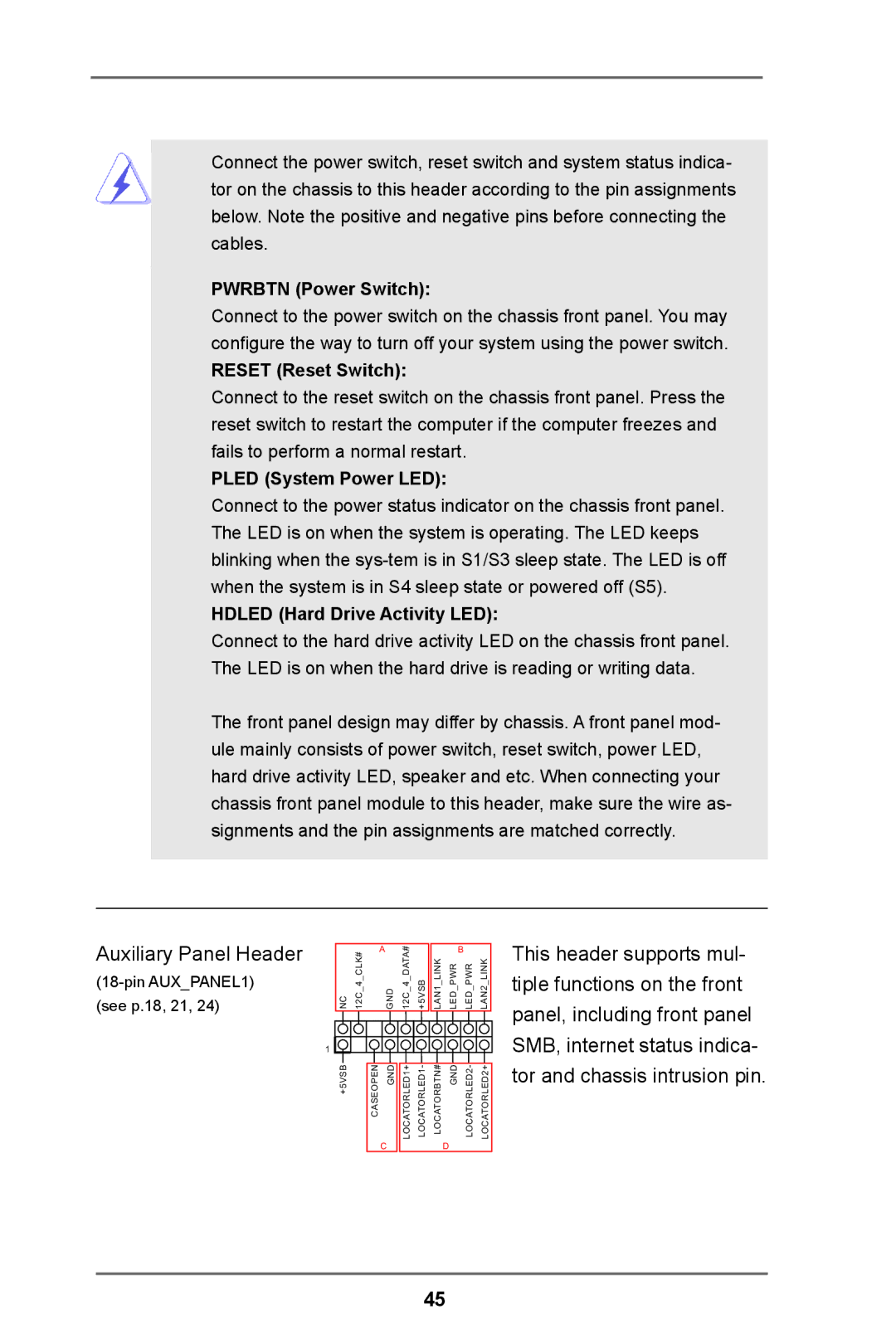
Auxiliary Panel Header
(18-pin AUX_PANEL1) (see p.18, 21, 24)
NC 12C 4 CLK# | A | 12C 4 DATA# |
|
|
| B |
|
GND | +5VSB | LAN1 LINK | LED PWR | LED PWR | LAN2 LINK | ||
1 |
|
|
|
|
|
|
|
+5VSB | CASEOPEN GND | LOCATORLED1+ | LOCATORLED1- | LOCATORBTN# | GND | LOCATORLED2- | LOCATORLED2+ |
| C |
|
|
| D |
|
|
This header supports mul- tiple functions on the front panel, including front panel SMB, internet status indica- tor and chassis intrusion pin.
45