2.7 Jumpers Setup
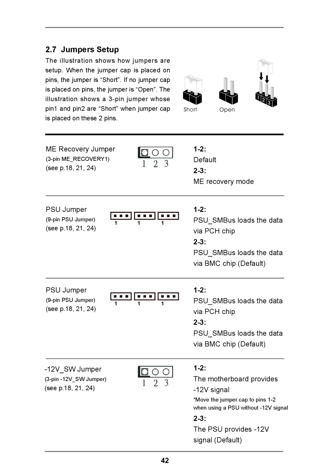
The illustration shows how jumpers are setup. When the jumper cap is placed on pins, the jumper is “Short”. If no jumper cap is placed on pins, the jumper is “Open”. The illustration shows a
ME Recovery Jumper | |
Default | |
(see p.18, 21, 24) | |
| |
| ME recovery mode |
PSU Jumper
(see p.18, 21, 24)
1
1
1
PSU_SMBus loads the data via PCH chip
PSU_SMBus loads the data via BMC chip (Default)
PSU Jumper
(see p.18, 21, 24)
1
1
1
PSU_SMBus loads the data via PCH chip
PSU_SMBus loads the data via BMC chip (Default)
The motherboard provides | |
(see p.18, 21, 24) | |
| *Move the jumper cap to pins |
| when using a PSU without |
The PSU provides
42