2.8 Surround Display Feature
This motherboard supports Surround Display upgrade. With the external
..\ Surround Display Information
2.9 Jumpers Setup
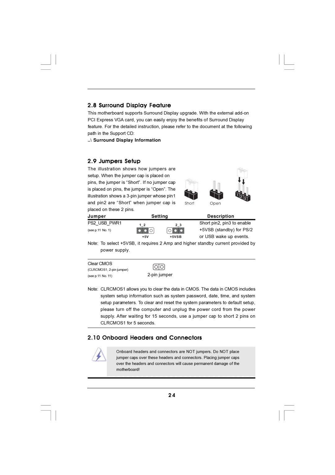
The illustration shows how jumpers are setup. When the jumper cap is placed on pins, the jumper is “Short”. If no jumper cap is placed on pins, the jumper is “Open”. The illustration shows a
Jumper |
| Setting | Description |
PS2_USB_PWR1 | 1_2 | 2_3 | Short pin2, pin3 to enable |
(see p.11 No. 1) |
|
| +5VSB (standby) for PS/2 |
| +5V | +5VSB | or USB wake up events. |
Note: To select +5VSB, it requires 2 Amp and higher standby current provided by power supply.
Clear CMOS (CLRCMOS1,
(see p.11 No. 11) |
Note: CLRCMOS1 allows you to clear the data in CMOS. The data in CMOS includes system setup information such as system password, date, time, and system setup parameters. To clear and reset the system parameters to default setup, please turn off the computer and unplug the power cord from the power supply. After waiting for 15 seconds, use a jumper cap to short 2 pins on CLRCMOS1 for 5 seconds.
2.10 Onboard Headers and Connectors
Onboard headers and connectors are NOT jumpers. Do NOT place jumper caps over these headers and connectors. Placing jumper caps over the headers and connectors will cause permanent damage of the motherboard!
2 4