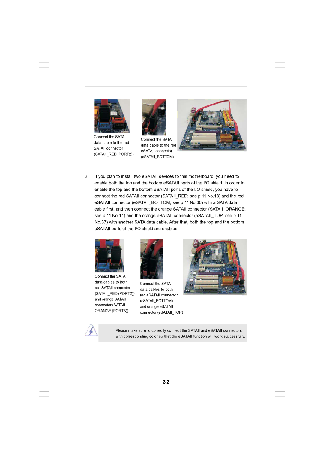
Connect the SATA data cable to the red SATAII connector (SATAII_RED (PORT2))
Connect the SATA data cable to the red eSATAII connector (eSATAII_BOTTOM)
2.If you plan to install two eSATAII devices to this motherboard, you need to enable both the top and the bottom eSATAII ports of the I/O shield. In order to enable the top and the bottom eSATAII ports of the I/O shield, you have to connect the red SATAII connector (SATAII_RED; see p.11 No.13) and the red eSATAII connector (eSATAII_BOTTOM; see p.11 No.36) with a SATA data cable first, and then connect the orange SATAII connector (SATAII_ORANGE; see p.11 No.14) and the orange eSATAII connector (eSATAII_TOP; see p.11 No.37) with another SATA data cable. After that, both the top and the bottom eSATAII ports of the I/O shield are enabled.
Connect the SATA data cables to both red SATAII connector (SATAII_RED (PORT2)) and orange SATAII connector (SATAII_ ORANGE (PORT3))
Connect the SATA data cables to both red eSATAII connector (eSATAII_BOTTOM) and orange eSATAII connector (eSATAII_TOP)
Please make sure to correctly connect the SATAII and eSATAII connectors with corresponding color so that the eSATAII function will work successfully.
3 2