•You must install Windows® 2000 Service Pack 4 or the Windows® XP Service Pack 1 before using Serial ATA hard disk drives. The Serial ATA RAID feature (RAID 0/RAID 1/RAID 5/RAID 10) is available only if you are using Windows® 2000/XP or later version.
•When using the connectors in Standard IDE mode, connect the primary (boot) hard disk drive to the SATA1/2/5/6 connector. Refer to the table below for the recommended SATA hard disk drive connections.
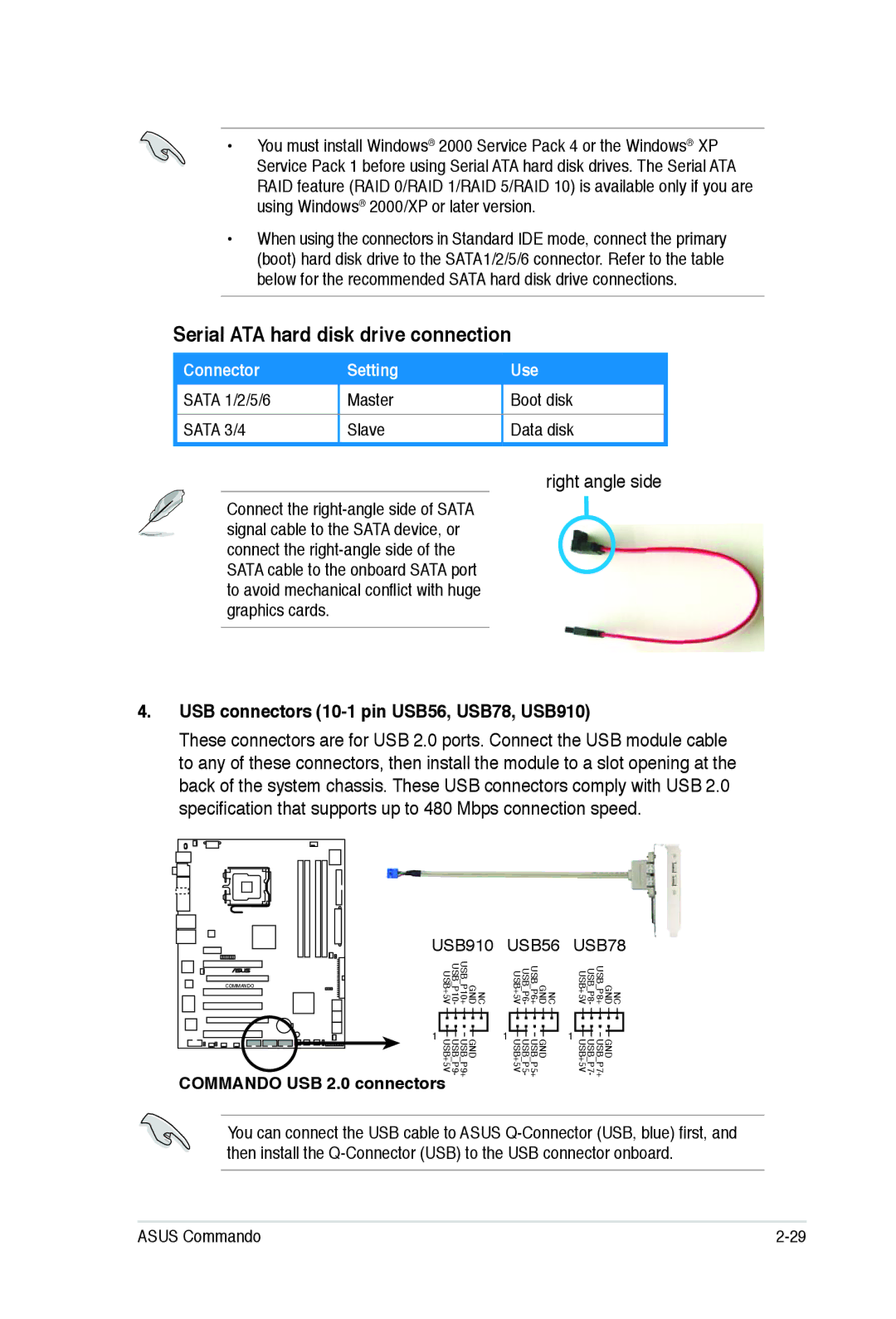
Serial ATA hard disk drive connection
Connector | Setting | Use |
SATA 1/2/5/6 | Master | Boot disk |
SATA 3/4 | Slave | Data disk |
right angle side
Connect the
4.USB connectors (10-1 pin USB56, USB78, USB910)
These connectors are for USB 2.0 ports. Connect the USB module cable to any of these connectors, then install the module to a slot opening at the back of the system chassis. These USB connectors comply with USB 2.0 specification that supports up to 480 Mbps connection speed.
| USB910 | USB56 | USB78 | |
|
| USB | USB | USB |
COMMANDO |
| USB | USB | USB |
| _ | _ | _ | |
|
| _P10 | _P6 | _P8 |
| NC GND P10+ - USB+5V | NC GND P6+ - USB+5V | NC GND P8+ - USB+5V | |
| 1 |
| 1 | 1 |
|
| GND USB USB | GND USB USB | GND USB USB |
|
| _ _ | _ _ | _ _ |
| P9 USB+5V | P5 USB+5V | P7 USB+5V | |
|
| - | - | - |
COMMANDO USB 2.0 connectors | P9+ | P5+ | P7+ | |
|
|
| ||
You can connect the USB cable to ASUS
ASUS Commando |