English
4.2 Functional Layout
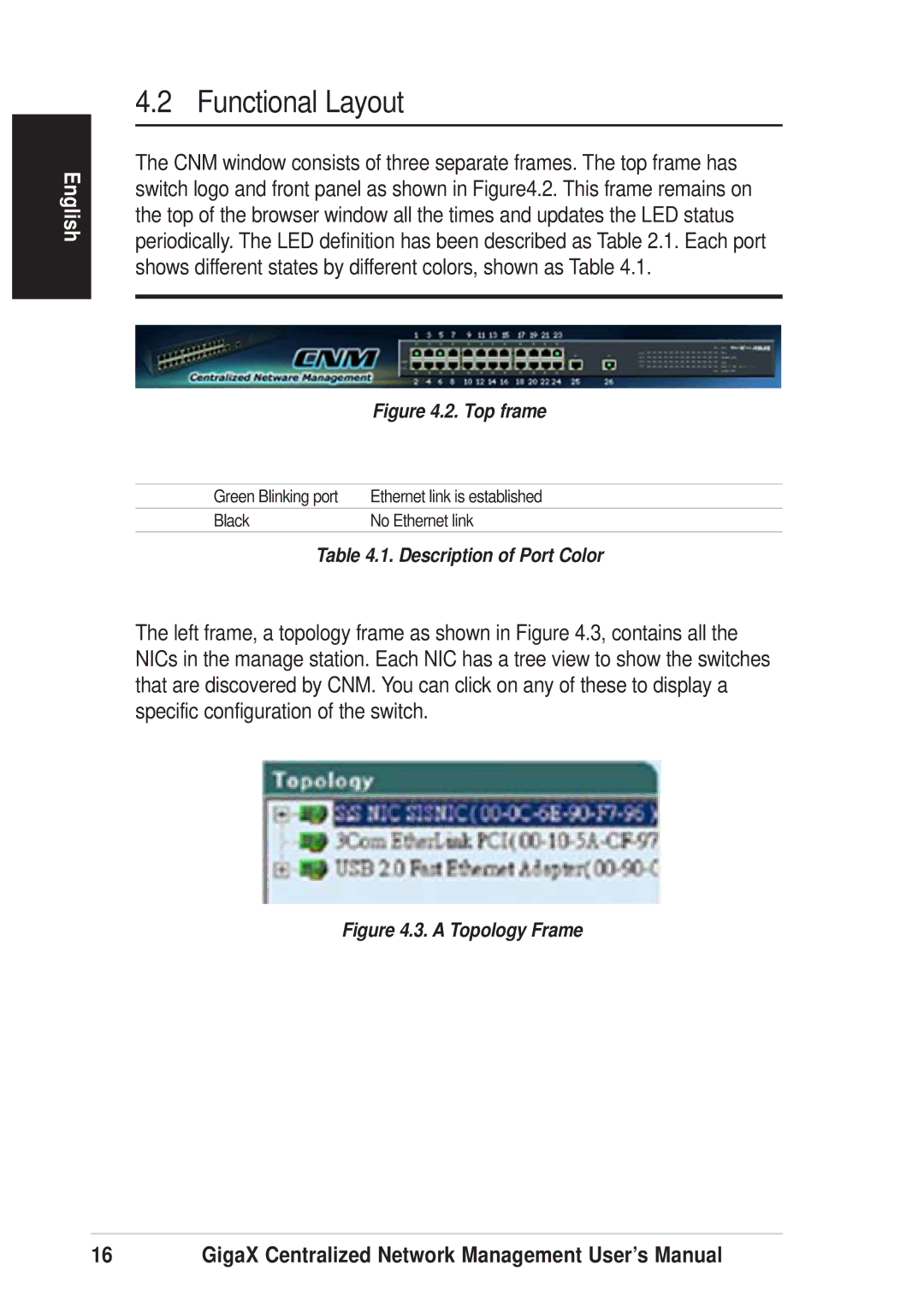
The CNM window consists of three separate frames. The top frame has switch logo and front panel as shown in Figure4.2. This frame remains on the top of the browser window all the times and updates the LED status periodically. The LED definition has been described as Table 2.1. Each port shows different states by different colors, shown as Table 4.1.
Figure 4.2. Top frame
Green Blinking port | Ethernet link is established |
Black | No Ethernet link |
Table 4.1. Description of Port Color
The left frame, a topology frame as shown in Figure 4.3, contains all the NICs in the manage station. Each NIC has a tree view to show the switches that are discovered by CNM. You can click on any of these to display a specific configuration of the switch.
Figure 4.3. A Topology Frame
16 | GigaX Centralized Network Management User’s Manual |