2.2 Front Panel
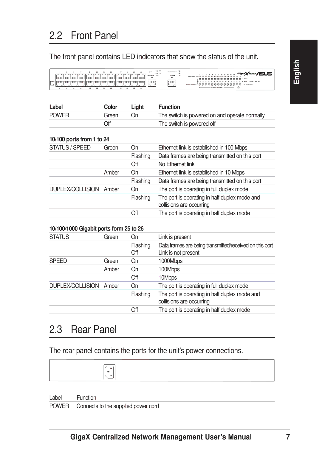
The front panel contains LED indicators that show the status of the unit.
English
Label | Color | Light | Function |
POWER | Green | On | The switch is powered on and operate normally |
| Off |
| The switch is powered off |
10/100 ports from 1 to 24 |
|
| |
STATUS / SPEED | Green | On | Ethernet link is established in 100 Mbps |
|
| Flashing | Data frames are being transmitted on this port |
|
| Off | No Ethernet link |
| Amber | On | Ethernet link is established in 10 Mbps |
|
| Flashing | Data frames are being transmitted on this port |
DUPLEX/COLLISION | Amber | On | The port is operating in full duplex mode |
|
| Flashing | The port is operating in half duplex mode and |
|
|
| collisions are occurring |
|
| Off | The port is operating in half duplex mode |
10/100/1000 Gigabit ports form 25 to 26 |
| ||
STATUS | Green | On | Link is present |
|
| Flashing | Data frames are being transmitted/received on this port |
|
| Off | Link is not present |
SPEED | Green | On | 1000Mbps |
| Amber | On | 100Mbps |
|
| Off | 10Mbps |
DUPLEX/COLLISION | Amber | On | The port is operating in full duplex mode |
|
| Flashing | The port is operating in half duplex mode and |
|
|
| collisions are occurring |
|
| Off | The port is operating in half duplex mode |
2.3 Rear Panel
The rear panel contains the ports for the unit’s power connections.
Label Function
POWER Connects to the supplied power cord
GigaX Centralized Network Management User’s Manual | 7 |
