Motherboard
Copyright 2006 ASUSTeK Computer INC. All Rights Reserved
E2732 First Edition August
Contents
Managing and updating your Bios
Bios setup
Software support
Installing an operating system Support CD information
Canadian Department of Communications Statement
Federal Communications Commission Statement
Electrical safety
Safety information
Operation safety
CPU
M2NBP-VM CSM specifications summary
TPM connector
Power Requirement Form Factor Support CD contents
Specifications are subject to change without notice
Product
Features and the new technologies it supports
Special features
Package contents
Welcome
Nvidia Quadro NVS210S GPU Nvidia nForce 430B MCP chipsets
AMD Cool ‘n’ Quiet Technology
DDR2 memory support
PCI Express interface
Serial ATA 3Gb/s technology
Gigabit LAN solution
USB 2.0 technology
High Definition Audio
Innovative Asus features
Onboard LED
Before you proceed
Motherboard layout
Motherboard overview
Screw holes
Placement direction
To install a CPU Locate the CPU socket on the motherboard
Installing the CPU
Central Processing Unit CPU
M2NBP-VM CSM CPU fan connector
Installing the heatsink and fan
Product introduction
Recommended Memory Configurations
Memory configurations
System memory
Overview
64-bit
DDR2-667 MHz capability
Qualified Vendors Lists QVL DDR2-800 MHz capability
DDR2-533 MHz capability
Removing a Dimm
Installing a Dimm
Configuring an expansion card
Installing an expansion card
To install an expansion card
Expansion slots
IRQ assignments for this motherboard
Standard interrupt assignments
These IRQs are usually available for ISA or PCI devices
PCI Express x1 slot
PCI slots
PCI Express x16 slot
Clear RTC RAM Clrtc
Jumpers
USBPW56
USB device wake-up 3-pin USBPW12, USBPW34, USBPW56, USBPW78
Keyboard power 3-pin Kbpwr
Rear panel connectors
Connectors
LAN port LED indications
Headset 6-speaker
Audio 2, 4, or 6-channel configuration
Floppy disk drive connector 34-1 pin Floppy
Internal connectors
Chassis intrusion connector 4-1 pin Chassis
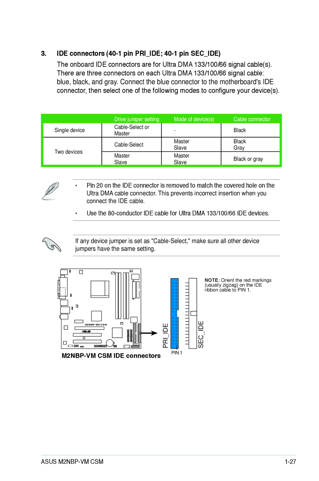
IDE connectors 40-1 pin Priide 40-1 pin Secide
M2NBP-VM CSM Sata connectors
Serial ATA connectors 7-pin SATA1, SATA2, SATA3, SATA4
Digital audio connector 4-1 pin Spdifout
Optical drive audio in connector 4-pin CD
USB connectors 10-1 pin USB56, USB78
M2NBP-VM CSM TPM connector
TPM connector 20-1 pin TPM
Front panel audio connector 10-1 pin Aafp
Serial port connector 10-1 pin COM1
Type has 24-pin and 4-pin power plugs
ATX power connectors 24-pin EATXPWR, 4-pin ATX12V
System power LED Pwrled
System panel connector 20-1 pin Panel
Power/Soft-off button Pwrbtn
Reset button Reset
Bios setup
Asus Update utility
Managing and updating your Bios
Installing Asus Update
Updating the Bios through the Internet
Locate the Bios file from the Open window, then click Open
Updating the Bios through a Bios file
DOS environment
Creating a bootable floppy disk
Asus EZ Flash 2 utility
Bios Flash Utility
Updating the Bios
Enter. The Award Bios
FAT 16/12 format
Utility displays a
No Update
Complete
Write OK
Now Backup Syetem Bios to File Message Please wait
Saving the current Bios file
Message Please wait
Recovering the Bios from the support CD
Asus CrashFree Bios 2 utility
Bios setup program
Configuration
Bios menu screen
Settings
Menu bar
Menu items
Configuration fields
Sub-menu items
Pop-up window
Advanced Power
General help
Tools Exit
System Time
Main menu
System Date Day xx/xx/xxxx
Legacy Diskette a 1.44M, 3.5
Primary and Secondary IDE Master/Slave
Access Mode Auto
Udma Mode Auto
PIO Mode Auto
Transfer Mode
Capacity
Extended Drive Auto
Sata 1/2/3/4
Extended IDE Drive
Installed Memory xxx MB
HDD Smart Monitoring Disabled
Usable Memory XXX MB
Landing Zone
AI Tuning Auto
JumperFree Configuration
When overclocking
Advanced menu
CPU Frequency XXX value is auto-detected
Overclock Options Disabled
DDR2 Voltage Control Auto
Post Check LAN Cable Enabled
CPU Configuration
Dram Configuration
AI Net2
Configuration options Auto 3 4 5
Configuration options Auto3 4 5
Configuration options Auto 5 6 7 ~
Configuration options Auto 11 12 13 ~
Chipset
Plug & Play O/S No
PCIPnP
Primary Display Adapter PCI-E
Resources Controlled By Auto
IDE Function Setup
Onboard Devices Configuration
IDE Function Setup
OnChip IDE Channel0 Enabled
RAID Enable Disabled
Nvraid Configuration
Onboard nVidia LAN Enabled
USB Configuration
OnBoard LAN Boot ROM Disabled
HD Audio Enabled
ECP Mode Use DMA
Parallel Port Mode EPP
Allows selection of ECP Mode. Configuration options 1
Serial Port1 Address 3F8/IRQ4
Acpi Apic Support Enabled
Power menu
APM Configuration
Acpi Suspend Type S1&S3
HDD Down In Suspend Disabled
Restore on AC Power Loss Disabled
Power Up On By PCI/PCIE Devices Disabled
Power On By External Modems Disabled
Power On By PS/2 Mouse Disabled
Alarm Time hhmm Disabled
Power On By PS/2 Keyboard Disabled
Configuration options Disabled Space Bar Ctrl-ESC Power Key
CPU Temperature, M/B Temperature
Fan Controller Disabled
Hardware Monitor
Vcore Voltage, 3.3V Voltage, 5V Voltage, 12V Voltage
Boot Device Priority
Boot menu
1st ~ 4th Boot Device Removable
Removable Drives
Hard Disk Drives
Boot Settings Configuration
Cdrom Drives
2nd Slave
Quick Boot Enabled
Case Open Warning Enabled
Boot Up Floppy Seek Disabled
Bootup Num-Lock On
Halt On All, But Keyboard
Full Screen Logo Enabled
Supervisor Password
Supervisor Password/User Password
Security
Press any key to continue
Security Chip Disabled
Password Check
ASUSTek EZ Flash 2 Bios Rrom Utility B316
Main Advanced Power Boot Tools Exit
Tools menu
Asus EZ Flash
Exit menu
Main Advanced Power Boot Tools
Exit & Save Changes
Exit & Discard Changes
Discard Changes
Load Setup Defaults
Support
Support CD information
Installing an operating system
Running the support CD
Nvidia nForce Chipset Driver
Drivers menu
SoundMAX ADI1986A Audio Driver
AMD Cool ‘n’ Quiet Driver
Utilities menu
Asus Update
Asus PC Probe
Adobe Acrobat Reader Asus Cool ‘n’ Quiet Utility
Nvidia 32bit WinXP Sata RAID Driver
Make Disk menu
Nvidia 64 bit WinXP Sata RAID Driver
Make Disk menu allows you to make a RAID driver disk
Nvidia RAID User’s Manual
Manual menu
Nvidia Network User’s Manual
Allows you to open the Nvidia RAID user’s manual
Asus Contact information
Displays the support CD contents in graphical format
Displays the general specifications of the motherboard
Other information
Motherboard Info
Technical support Form
Displays the contents of the support CD in text format
Filelist
Creating a RAID driver disk