Appendix
Table 5. BNC Connectors
Pin |
|
| Signals |
|
|
|
|
|
|
Assignment |
| Composite Sync. | Separate Sync. | |
|
|
|
|
|
R | Red |
| Red | Red |
G | Green+Sync. |
| Green+Sync. | Green |
B | Blue |
| Blue | Blue |
H/V | NC |
| H/V Comp. Sync. | |
V | NC |
| NC | |
|
|
|
|
|
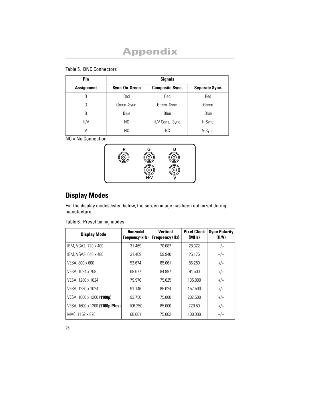
NC = No Connection |
|
|
|
|
| R | G | B |
|
H/VV
Display Modes
For the display modes listed below, the screen image has been optimized during manufacture.
Table 6. Preset timing modes
Display Mode | Horizontal | Vertical | Pixel Clock | Sync Polarity | |
Frequency (kHz) | Frequency (Hz) | (MHz) | (H/V) | ||
| |||||
|
|
|
|
| |
IBM, VGA2, 720 x 400 | 31.469 | 70.087 | 28.322 | ||
IBM, VGA3, 640 x 480 | 31.469 | 59.940 | 25.175 | ||
VESA, 800 x 600 | 53.674 | 85.061 | 56.250 | +/+ | |
VESA, 1024 x 768 | 68.677 | 84.997 | 94.500 | +/+ | |
VESA, 1280 x 1024 | 79.976 | 75.025 | 135.000 | +/+ | |
VESA, 1280 x 1024 | 91.146 | 85.024 | 157.500 | +/+ | |
VESA, 1600 x 1200 (1100p) | 93.750 | 75.000 | 202.500 | +/+ | |
VESA, 1600 x 1200 (1100p Plus) | 106.250 | 85.000 | 229.50 | +/+ | |
MAC. 1152 x 870 | 68.681 | 75.062 | 100.000 | ||
|
|
|
|
|
26