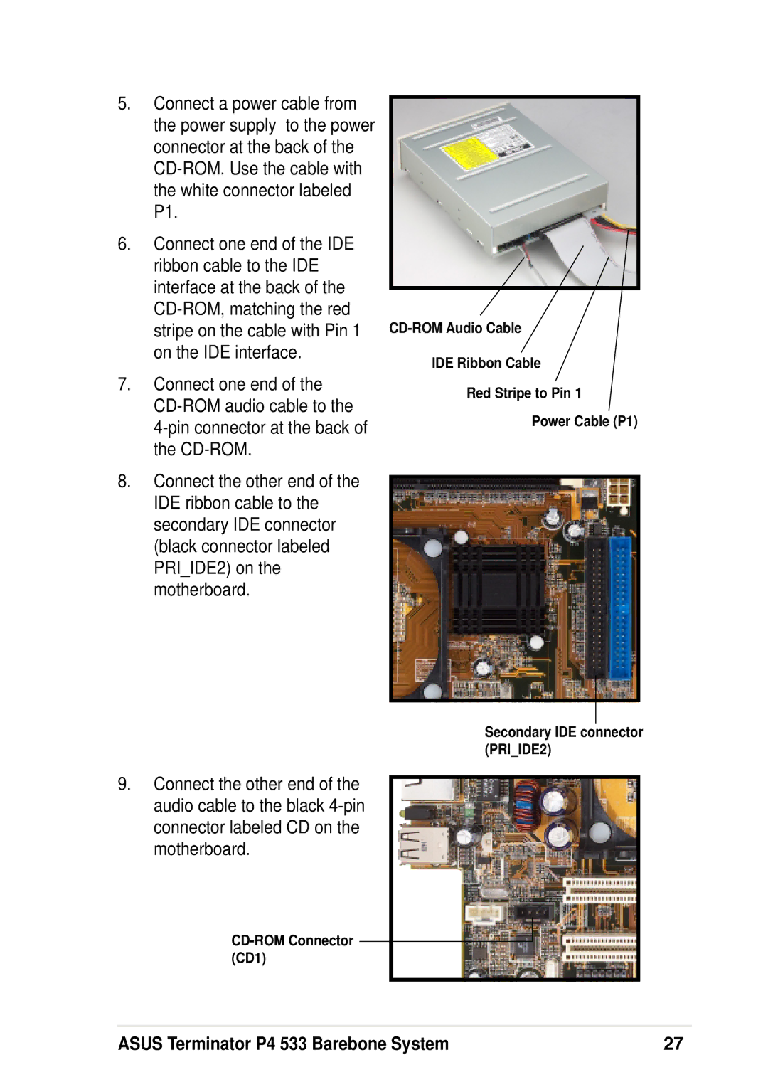
5.Connect a power cable from the power supply to the power connector at the back of the
6.Connect one end of the IDE ribbon cable to the IDE interface at the back of the
7.Connect one end of the
4-pin connector at the back of the CD-ROM.
8.Connect the other end of the IDE ribbon cable to the secondary IDE connector (black connector labeled PRI_IDE2) on the motherboard.
IDE Ribbon Cable
Red Stripe to Pin 1
Power Cable (P1)
9.Connect the other end of the audio cable to the black
Secondary IDE connector (PRI_IDE2)
ASUS Terminator P4 533 Barebone System | 27 |