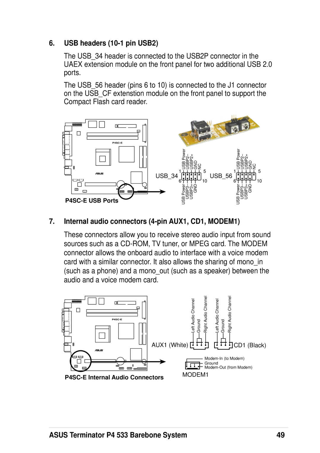
6.USB headers (10-1 pin USB2)
The USB_34 header is connected to the USB2P connector in the UAEX extension module on the front panel for two additional USB 2.0 ports.
The USB_56 header (pins 6 to 10) is connected to the J1 connector on the USB_CF extenstion module on the front panel to support the Compact Flash card reader.
|
USB Power | USBP2– | USBP2+ | GND NC | USB Power | USBP2– | USBP2+ | GND NC |
1 |
|
| 5 | 1 |
|
| 5 |
USB_34 |
|
|
| USB_56 |
|
|
|
6 | USBP3– |
| 10 | 6 | USBP3– |
| 10 |
USB Power | USBP3+ | GND | USB Power | USBP3+ | GND |
7.Internal audio connectors (4-pin AUX1, CD1, MODEM1)
These connectors allow you to receive stereo audio input from sound sources such as a
Left Audio Channel | Ground | Right Audio Channel |
AUX1 (White) ![]()
![]()
![]()
![]()
Left Audio Channel Ground | Right Audio Channel | ||||||||
|
|
|
|
|
|
|
|
| CD1 (Black) |
|
|
|
|
|
|
|
|
| |
|
|
|
|
|
|
|
| ||
|
|
|
|
|
|
|
|
| |
![]() Ground
Ground
![]()
![]()
![]()
![]()
MODEM1 | |
|
ASUS Terminator P4 533 Barebone System | 49 |
