3.8 Connectors
This section describes and illustrates the connectors on the motherboard.
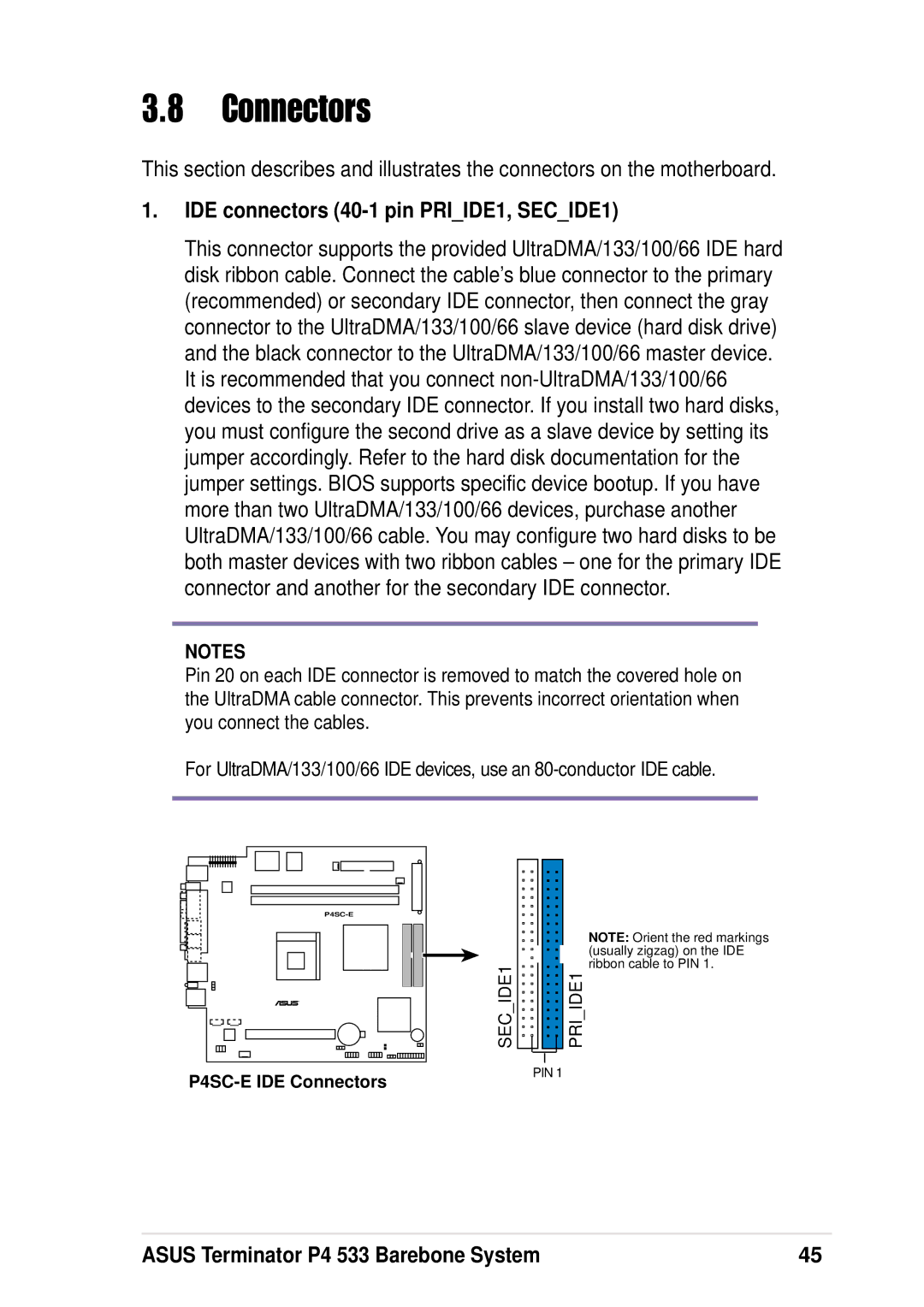
1.IDE connectors (40-1 pin PRI_IDE1, SEC_IDE1)
This connector supports the provided UltraDMA/133/100/66 IDE hard disk ribbon cable. Connect the cable’s blue connector to the primary (recommended) or secondary IDE connector, then connect the gray connector to the UltraDMA/133/100/66 slave device (hard disk drive) and the black connector to the UltraDMA/133/100/66 master device. It is recommended that you connect
NOTES
Pin 20 on each IDE connector is removed to match the covered hole on the UltraDMA cable connector. This prevents incorrect orientation when you connect the cables.
For UltraDMA/133/100/66 IDE devices, use an
|
|
|
|
|
| NOTE: Orient the red markings |
|
|
|
|
|
| (usually zigzag) on the IDE |
SEC IDE1 |
|
|
|
|
| ribbon cable to PIN 1. |
|
|
|
|
| ||
|
|
|
|
| PRI IDE1 | |
|
|
|
|
| ||
|
|
|
|
|
|
|
PIN 1
ASUS Terminator P4 533 Barebone System | 45 |