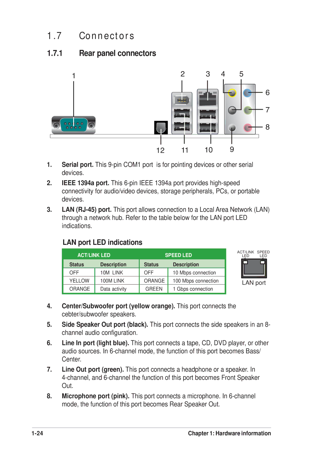
1.7Connectors
1.7.1Rear panel connectors
1 | 2 | 3 | 4 | 5 |
6
7
8
12 11 10 9
1.Serial port. This
2.IEEE 1394a port. This
3.LAN
LAN port LED indications
| ACT/LINK LED |
| SPEED LED | ACT/LINK | SPEED | ||||||||
|
| ||||||||||||
|
|
| LED | LED | |||||||||
|
|
|
|
|
|
|
|
|
|
|
|
|
|
| Status | Description | Status |
| Description |
|
|
|
|
|
|
|
|
|
|
|
|
|
|
|
|
|
| ||||
| OFF | 10M LINK | OFF |
| 10 Mbps connection |
|
|
|
|
|
|
|
|
| YELLOW | 100M LINK | ORANGE |
| 100 Mbps connection |
| LAN port |
| |||||
| ORANGE | Data activity | GREEN |
| 1 Gbps connection |
| |||||||
|
|
|
|
|
|
|
|
|
| ||||
|
|
|
|
|
|
|
|
|
|
|
|
|
|
4.Center/Subwoofer port (yellow orange). This port connects the cebter/subwoofer speakers.
5.Side Speaker Out port (black). This port connects the side speakers in an 8- channel audio configuration.
6.Line In port (light blue). This port connects a tape, CD, DVD player, or other audio sources. In
7.Line Out port (green). This port connects a headphone or a speaker. In
8.Microphone port (pink). This port connects a microphone. In
Chapter 1: Hardware information |