Asus P5SD2-FM manual System panel connector 10-1 pin Fpanel, System power LED Green 2-pin Pled

Models: P5SD2-FM

1 68
Download 68 pages 8.68 Kb
Page 41
Image 41

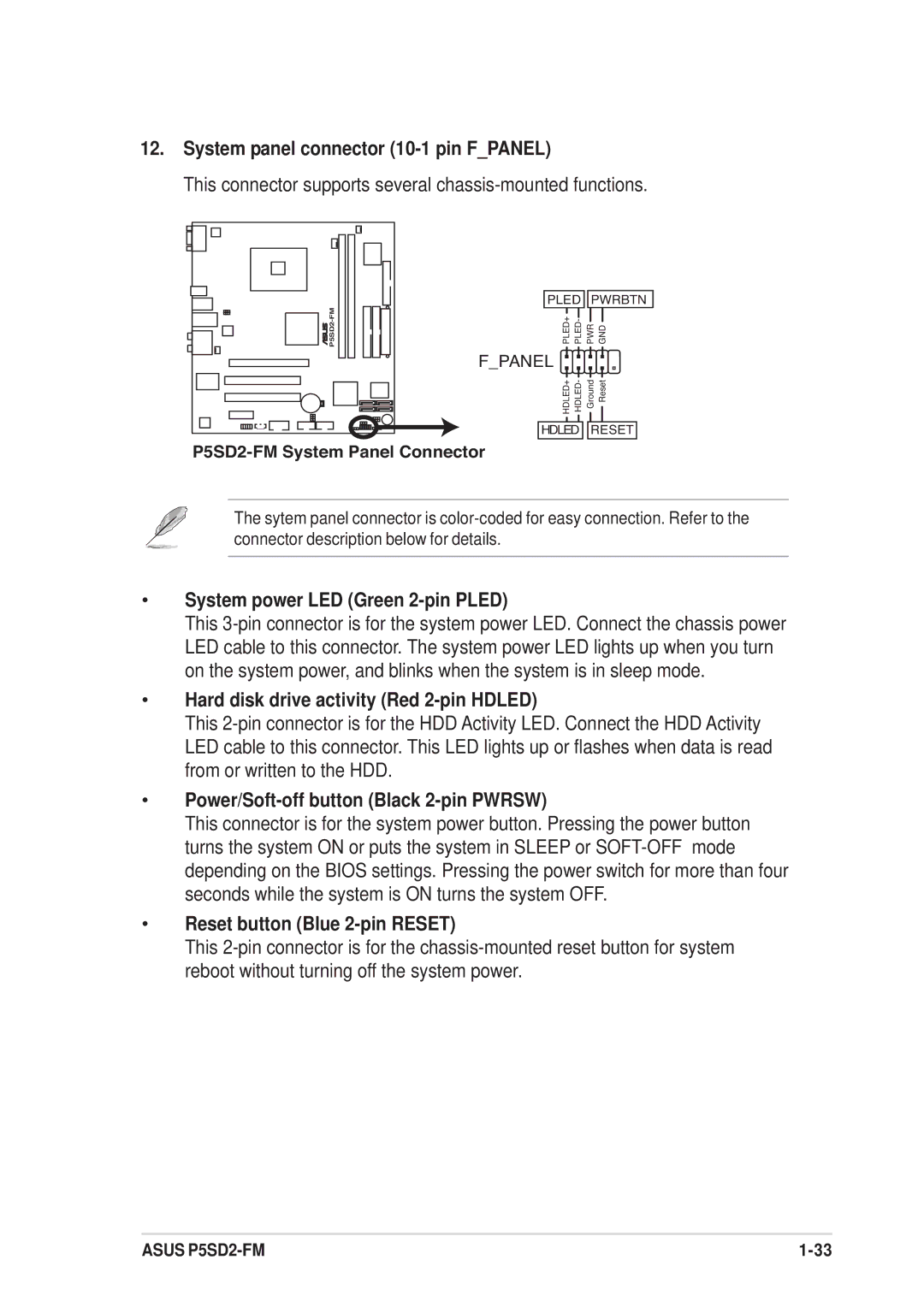
12.System panel connector (10-1 pin F_PANEL)

This connector supports several chassis-mounted functions.

FM-P5SD2

r

PLED

PWRBTN

PLED+ PLED-

PWR GND

F_PANEL


HDLED+ HDLED-

Ground Reset

HDLED RESET

P5SD2-FM System Panel Connector

The sytem panel connector is color-coded for easy connection. Refer to the connector description below for details.

System power LED (Green 2-pin PLED)

This 3-pin connector is for the system power LED. Connect the chassis power LED cable to this connector. The system power LED lights up when you turn on the system power, and blinks when the system is in sleep mode.

Hard disk drive activity (Red 2-pin HDLED)

This 2-pin connector is for the HDD Activity LED. Connect the HDD Activity LED cable to this connector. This LED lights up or flashes when data is read from or written to the HDD.

Power/Soft-off button (Black 2-pin PWRSW)

This connector is for the system power button. Pressing the power button turns the system ON or puts the system in SLEEP or SOFT-OFF mode depending on the BIOS settings. Pressing the power switch for more than four seconds while the system is ON turns the system OFF.

Reset button (Blue 2-pin RESET)

This 2-pin connector is for the chassis-mounted reset button for system reboot without turning off the system power.

ASUS P5SD2-FM

1-33

Page 41
Image 41
Asus P5SD2-FM System panel connector 10-1 pin Fpanel, System power LED Green 2-pin Pled, Reset button Blue 2-pin Reset