![]() 26-Port Dual Web Rack Switch The Switch is equipped with two
26-Port Dual Web Rack Switch The Switch is equipped with two
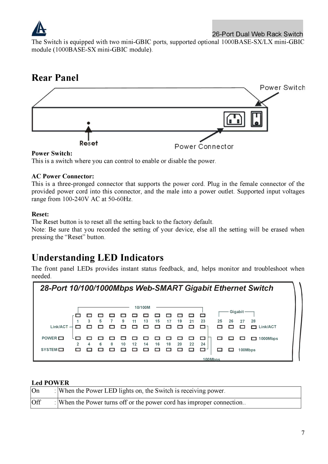
Rear Panel
Power Switch:
This is a switch where you can control to enable or disable the power.
AC Power Connector:
This is a
Reset:
The Reset button is to reset all the setting back to the factory default.
Note: Be sure that you recorded the setting of your device, else all the setting will be erased when pressing the “Reset” button.
Understanding LED Indicators
The front panel LEDs provides instant status feedback, and, helps monitor and troubleshoot when needed.
|
|
|
|
|
|
|
|
| 10/100M |
|
|
|
|
|
|
|
|
| Gigabit |
|
|
| |||
|
|
|
|
|
|
|
|
|
|
|
|
|
|
|
|
|
|
|
|
|
|
|
| ||
Link/ACT | 1 | 3 |
| 5 | 7 |
| 9 | 11 |
| 13 | 15 | 17 |
| 19 | 21 |
| 23 |
| 25 | 26 | 27 | 28 | Link/ACT | ||
|
|
|
|
|
|
|
|
|
|
|
|
|
|
|
|
|
|
|
|
|
|
| |||
POWER | FX | 1 | 2 | 3 | 4 | 5 | 6 | 7 | 8 | 9 | 10 | 11 | 12 | 13 | 14 | 15 | 16 | 17 | 18 | 19 | 20 | 21 | 22 | 23 | 24 |
Link/ACT |
|
|
|
|
|
|
|
|
|
|
|
|
|
|
|
|
|
|
|
|
|
|
| 1000Mbps | |
POWER |
|
|
|
|
|
|
|
|
|
|
|
|
|
|
|
|
|
|
|
|
|
|
|
| |
SYSTEM | FDX | 2 | 4 |
|
| 8 |
| 10 | 12 |
| 14 | 16 | 18 |
| 20 | 22 |
| 24 |
|
|
|
|
|
|
|
|
|
|
|
|
|
|
|
|
|
|
|
|
|
|
|
|
|
|
| 100Mbps |
| ||||
SYSTEM |
|
|
|
|
|
|
|
|
|
|
|
|
|
|
|
|
|
|
|
|
|
| |||
|
|
|
|
|
|
|
|
|
|
|
|
|
|
|
|
|
| 100Mbps |
|
|
|
|
| ||
Led POWER
On | : | When the Power LED lights on, the Switch is receiving power. |
|
|
|
Off | : | When the Power turns off or the power cord has improper connection.. |
|
|
|
7