INSTALLATION
The unit can be installed horizontally, vertically or at a 45° angle. The position of the
CAUTION: After setting the
HORIZONTAL INSTALLATION Set the left and right
position "H"
45 | H |
| |
V |
|
VERTICAL INSTALLAITON
Set the left and right
V | 45 |
position "V" | H |
45° ANGLE INSTALLATION Set the left and right
position "45°"
| 4 |
|
V | 5 | H |
|
|
45°
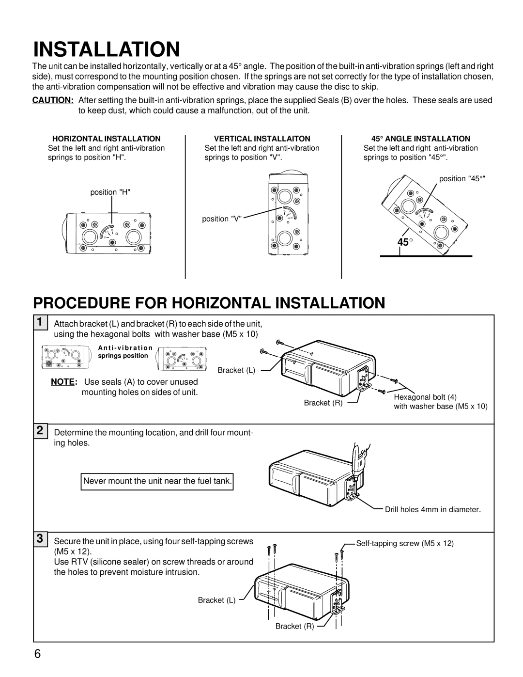
PROCEDURE FOR HORIZONTAL INSTALLATION
1
2
Attach bracket (L) and bracket (R) to each side of the unit, using the hexagonal bolts with washer base (M5 x 10)
A n t i - v i b r a t i o n
H 45 | springs position |
|
|
V | 45 | H | |
|
| V |
|
|
|
| Bracket (L) |
NOTE: Use seals (A) to cover unused |
|
|
mounting holes on sides of unit. |
| Hexagonal bolt (4) |
| Bracket (R) | |
| with washer base (M5 x 10) | |
|
|
Determine the mounting location, and drill four mount- ing holes.
Never mount the unit near the fuel tank.
Drill holes 4mm in diameter.
3 Secure the unit in place, using four
Use RTV (silicone sealer) on screw threads or around the holes to prevent moisture intrusion.
Bracket (L)
![]() Self-tapping
Self-tapping
Bracket (R) ![]()
6