Manuals
/
Avaya
/
Computer Equipment
/
Switch
Avaya
P3343T-ML
manual
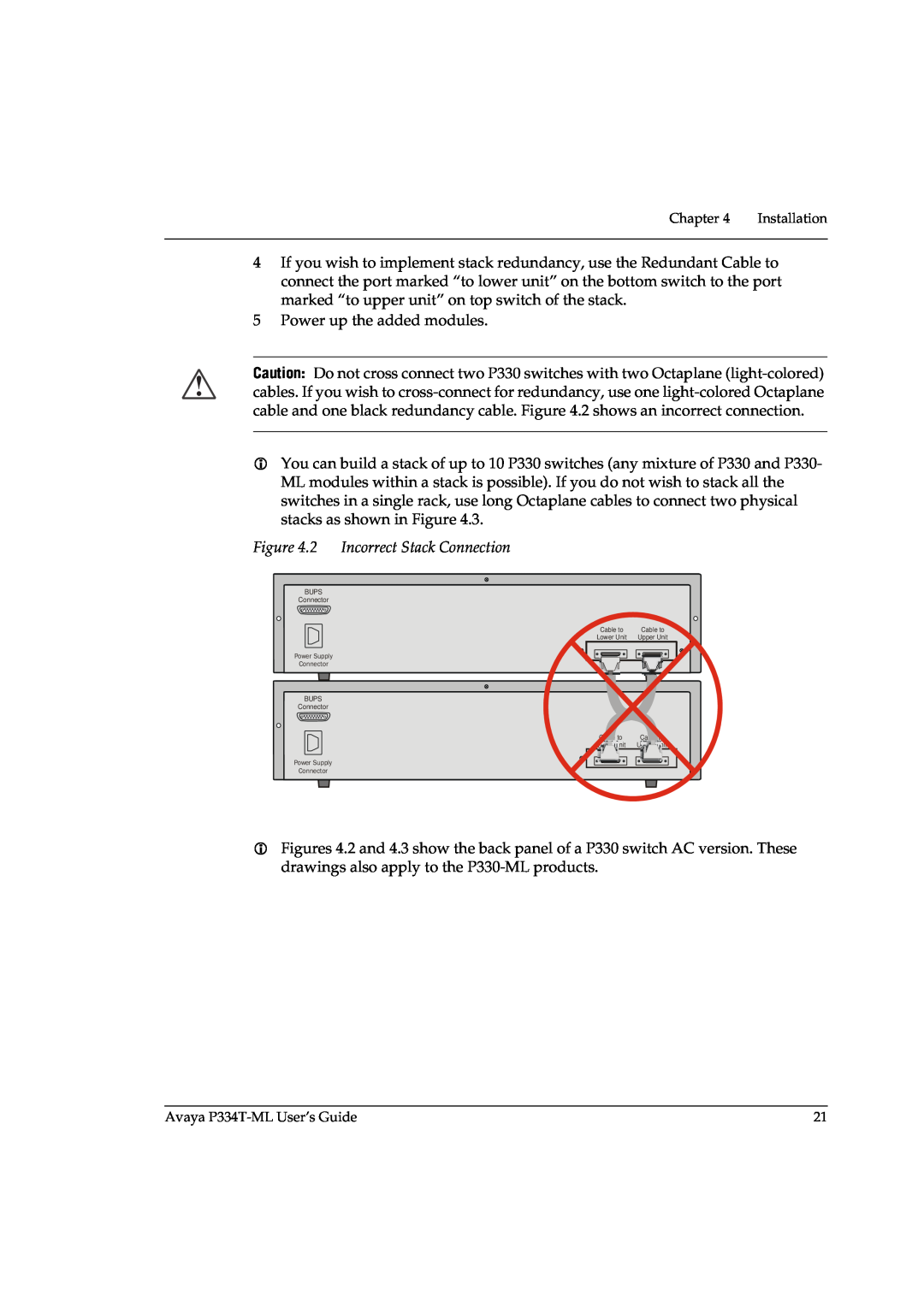
Power up the added modules
Models:
P3343T-ML
1
37
178
178
Download
178 pages
4.71 Kb
34
35
36
37
38
39
40
41
Specs
Install
Password
set port point-to-point admin
Warranty
Maintenance
Configuration
Establishing Switch Access
Command Line Interface CLI
BUPS-ML Input Connector
Page 37
Image 37
Page 36
Page 38
Page 37
Image 37
Page 36
Page 38
Contents
SOFTWARE VERSION
STACKABLE SWITCH
Installation and Configuration Guide
AVAYA P334T-ML
Document no
avaya.com
Section
Contents
Overview
Installation
Configuring the Terminal Serial Port Parameters
Configuration
Ingress VLAN Security
Port Mirroring Constraints
Troubleshooting and Maintenance
Chapter 15 Updating the Software
Safety Information
Before you Install the P330-ML
Preface
FCC Notice
Notes, Cautions, and Warnings
Warranty
Avaya Support
Avaya P334T-ML User’s Guide
SECTION 1 OVERVIEW
Page
Avaya P334T-ML Overview
Avaya P334T-ML Features
Chapter
Introduction
Command Line Interface CLI
Layer 3 Features P330-ML
Network Management and Monitoring
Device Manager Embedded Web
Port Mirroring
Avaya Integrated Manager
SMON
Fans, Power Supply, and BUPS-ML Monitoring
Avaya P330 Standards Supported
Standards and Compatibility
IEEE
IETF - Layer
IETF - Network Monitoring
P334T-ML Switch
Specifications
Power Requirements
Physical
Safety - AC Version
Safety
Safety - DC Version
EMC Emissions
Interfaces
Stacking Sub-module
Basic MTBF
Approved SFF/SFP GBIC Transceivers
Safety Information
Specifications
Installation
To Install the SFF/SFP GBIC transceiver
To Remove the SFF/SFP GBIC transceiver
Agency Approval
Gigabit Fiber Optic Cabling
Console Pin Assignments
Avaya P334T-ML User’s Guide
SECTION 2 INSTALLATION
Page
Required Tools
Installation
Site Preparation
Power Requirements - DC
Table 4.2 Power Requirements - AC
Rack Mounting Optional
Connecting Stacked Switches
Installing the X330STK-ML Stacking Sub-Module Optional
To connect stacked switches
5 Power up the added modules
X330SC
X330RC
X330LC
Making Connections to Network Equipment
Connecting Cables to Network Equipment
Prerequisites
Page
Powering On - Avaya P330 Module AC
Powering Up the Avaya P330
Powering On - Avaya P330 Switch DC
Post-Installation
Avaya P334T-ML Front Panel
Avaya P334T-ML Front and Rear Panels
LED Name
P334T-ML LEDs
Chapter 6 Avaya P334T-ML Front and Rear Panels
Avaya P334T-ML LED Descriptions Continued
BUPS-ML connector cover plate removed
Avaya P334T-ML Back Panel
Table 6.2 Avaya P334T-ML - - Select buttons
Figure 6.4 P334T-ML AC version Back Panel with Stacking Sub-module
Figure 6.6 BUPS-ML Input Connector Sticker
BUPS-ML Input Connector
Configuring the Terminal Serial Port Parameters
Establishing Switch Access
Connecting a Terminal to the Avaya P330 Serial port
Establishing a Serial Connection
Assigning P330’s IP Stack Address
P330 Sessions
session router
The mode can be either switch, router, wan, atm, mgp
Establishing an SSH Connection
Establishing a Telnet Connection
set interface ppp enable
Connecting a Modem to the Console Port
Establishing a Modem PPP Connection with the P330
Overview
Entering the Supervisor Level
Security Levels
Entering the CLI
SNMP Support
User Authentication
Introduction to SNMP
control the P330
Users
Groups
Views
SNMP Commands
In order to
In order to
Introduction to SSH
SSH Protocol Support
Figure 8.1 SSH Session Establishment Process
SSH Commands
SCP Protocol Support
Introduction to RADIUS
RADIUS
User name and password authenticated? No Authentication Reject
User attempts login Local User account authenticated in switch? No
sent to switch
Authentication request sent to RADIUS Server
Radius Commands
Telnet Client Support
Telnet Commands
Introduction to Telnet
Recovery Password Commands
Recovery Password
Introduction
Allowed Managers
Allowed Managers CLI Commands
Allowed Managers Introduction
Allowed Protocols
Allowed Protocols CLI Commands
Allowed Protocols Introduction
no ip telnet-client
ip telnet-client enable
SECTION 3 CONFIGURATION
Page
Configuring the Switch
P330 Default Settings
Avaya P330 Default Settings
Function
Ports
1 Ensure that the other side is also set to Autonegotiation Enabled
Ports 51
Avaya P334T-ML User’s Guide
Basic Switch Configuration
Switch Configuration
Identifying the system
System Parameter Configuration
Operating parameters
Network Time Acquiring Protocols Parameter Configuration
Uploading and Downloading Device Configurations and Images
Layer 2 Configuration File
In order to
Layer 3 Configuration File
In order to
System Logging Introduction
System Logging
Applications
Sinks
Syslog Servers
Syslog Configuration CLI Commands
In order to
Monitoring CPU Utilization
Avaya P334T-ML User’s Guide
Overview
Avaya P330 Layer 2 Features
Ethernet
Configuring Ethernet Parameters
Fast Ethernet
Gigabit Ethernet
Gigabit Ethernet ports
MMMMMMSSSSSS MM-MM-MM-SS-SS-SS
Ethernet Configuration CLI Commands
Speed - 10/100 ports 1-48 1G ports 51
Ethernet Implementation in the Avaya P334T-ML
Priority queuing - 10/100 ports 4 queues 1G ports 2 queues
CAM size - 8K addresses
VLAN Overview
VLAN Configuration
Multi VLAN Binding
VLAN Tagging
Figure 11.3 illustrates these binding modes in P330
Automatic VLAN Learning
VLAN CLI Commands
Ingress VLAN Security
VLAN Implementation in the Avaya P334T-ML
How “Port Based” Authentication Works
Port Based Network Access Control PBNAC
PBNAC Implementation in the P330 Family
Configuring the P330 for PBNAC
PBNAC CLI Commands
In order to
Spanning Tree Protocol
Spanning Tree Protocol
Spanning Tree per Port
Rapid Spanning Tree Protocol RSTP
Spanning Tree Implementation in the P330 Family
Spanning Tree Protocol CLI Commands
set port point-to-point admin
Set the port point-to-point admin
admin and operational RSTP status
status
MAC Security Implementation in P330
MAC Security
MAC Security CLI Commands
MAC Aging CLI Commands
Configuring the P330 for MAC Aging
MAC Aging
LAG Overview
LAG CLI Commands
LAG Implementation in the Avaya P330 Family of Products
Port Redundancy Operation
Port Redundancy
Intermodule Port Redundancy
Port Redundancy CLI Commands
show intermodule port redundancy
display the intermodule
redundancy entry defined for the
IP Multicast Filtering
IP Multicast Implementation in the Avaya P334T-ML
IP Multicast CLI Commands
RMON
RMON CLI Commands
RMON Overview
In order to
SMON Overview
SMON
Port Mirroring CLI commands
Port Mirroring Configuration
Port Mirroring Overview
Port Mirroring Constraints
About Multilayer Policy
Multilayer Policy
Multilayer Policy Implementation in the P334T-ML
Configuring the P334T-ML for Multilayer Policy
Multilayer Policy CLI Commands
In order to
Implementation of Weighted Queuing in the P330-ML
Weighted Queuing
Weighted Queuing CLI Commands
Port Classification
Port Classification CLI Commands
Stack Health
Stack Redundancy
Implementation of Stack Health in the P330 Family
Initiate the stack health testing
Stack Health CLI Commands
procedure
set stack health
Avaya P334T-ML User’s Guide
What is Routing?
Avaya P330 Layer 3 Features
Figure 12.1 Routing
Forwarding
Routing Configuration
Multinetting Multiple Subnets per VLAN
IP Configuration CLI Commands
IP Configuration
set vlan Vlan-id name Vlan-name replacing Vlan-id by the
Assigning Initial Router Parameters
The Routerconfigure-ifinterface-name# prompt appears
Routerconfigure# interface interface-name
Routerconfigure-ifinterface-name# ip address ip- address netmask
Routerconfigure# interface interface-name# ip vlan vland-id
To obtain a License Key that enables routing features
Obtaining a Routing License Key
1 Go to http//license-lsg.avaya.com and click “request new license”
2 Enter the Certificate Key and Certificate Type 3 Click Next
6 View number of licenses left
4 Enter contact information once per certificate 5 Click Next
License Key CLI Commands
set license module license featureName
Activating a Routing License Key
Avaya P334T-ML User’s Guide
RIP Overview
RIP Routing Interchange Protocol Configuration
RIP2
RIP CLI Commands
Table 12.1 DIfferences Between RIP and RIP2
In order to
OSPF Overview
OSPF Open Shortest Path First Configuration
OSPF CLI Commands
Static Routing Configuration CLI Commands
Static Routing Configuration
Static Routing Overview
Route Preferences
Route Redistribution
Route Redistribution Commands
ARP Overview
ARP Address Resolution Protocol Table Configuration
The ARP Table
ARP CLI Commands
BOOTP/DHCP Overview
BOOTP/DHCP Dynamic Host Configuration Protocol Relay Configuration
BOOTP/DHCP CLI Commands
NetBIOS Overview
NetBIOS Re-broadcast Configuration
NetBIOS Re-broadcast Configuration CLI Commands
VRRP Overview
VRRP Virtual Router Redundancy Protocol Configuration
VRRP Configuration Example
Case #2
VRRP CLI Commands
In order to
SRRP Configuration Example
SRRP Configuration
SRRP Overview
SRRP CLI Commands
Policy Configuration Overview
Policy Configuration
Policy Configuration CLI Commands
In order to
Figure 12.4 Avaya P330 Policy
Policy Configuration Example
P330-1super# ip access-list 100 2 fwd3 tcp any host
P330-1super# ip access-list 100 1 fwd6 tcp 149.49.0.0 0.0.255.255 any
P330-1super# ip access-list 100 3 deny tcp host 192.168.5.33 any eq
IP Fragmentation and Reassembly Overview
IP Fragmentation and Reassembly
IP Fragmentation/Reassembly CLI Commands
SECTION 4 TROUBLESHOOTING AND MAINTENANCE
Page
Troubleshooting the Installation
Troubleshooting the Installation
Chapter 13 Troubleshooting the Installation
Replacing the Stacking Sub-module
Maintenance
Maintenance
Software Download
Updating the Software
Obtain Software Online
Downloading Software
Download New Version without Overwriting Existing Version
Top
Page
Image
Contents