Making the Connections
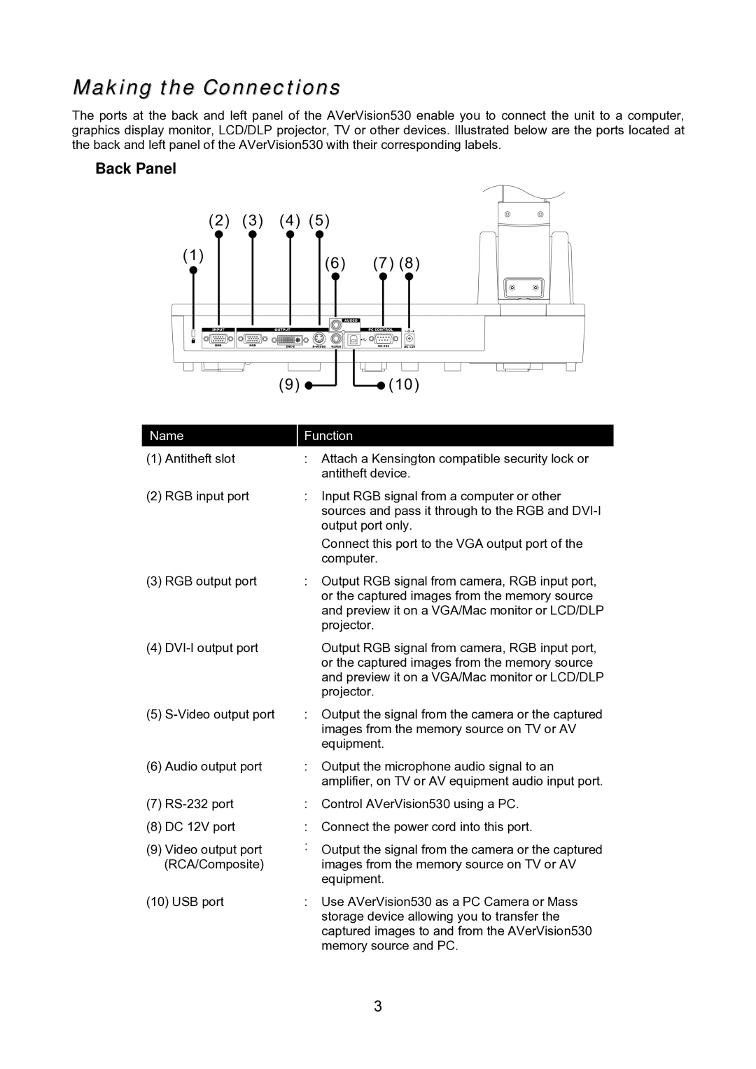
The ports at the back and left panel of the AVerVision530 enable you to connect the unit to a computer, graphics display monitor, LCD/DLP projector, TV or other devices. Illustrated below are the ports located at the back and left panel of the AVerVision530 with their corresponding labels.
Back Panel
(2) | (3) | (4) | (5) |
|
(1) |
|
| (6) | (7) (8) |
|
|
|
(9) | (10) |
Name
(1)Antitheft slot
(2)RGB input port
(3)RGB output port
(4)
(5)
(6)Audio output port
(7)
(8)DC 12V port
(9)Video output port (RCA/Composite)
(10)USB port
Function
:Attach a Kensington compatible security lock or antitheft device.
:Input RGB signal from a computer or other sources and pass it through to the RGB and
Connect this port to the VGA output port of the computer.
:Output RGB signal from camera, RGB input port, or the captured images from the memory source and preview it on a VGA/Mac monitor or LCD/DLP projector.
Output RGB signal from camera, RGB input port, or the captured images from the memory source and preview it on a VGA/Mac monitor or LCD/DLP projector.
:Output the signal from the camera or the captured images from the memory source on TV or AV equipment.
:Output the microphone audio signal to an amplifier, on TV or AV equipment audio input port.
:Control AVerVision530 using a PC.
:Connect the power cord into this port.
:Output the signal from the camera or the captured images from the memory source on TV or AV equipment.
:Use AVerVision530 as a PC Camera or Mass storage device allowing you to transfer the captured images to and from the AVerVision530 memory source and PC.
3