10LongView Wireless Installer/User Guide
LEDs
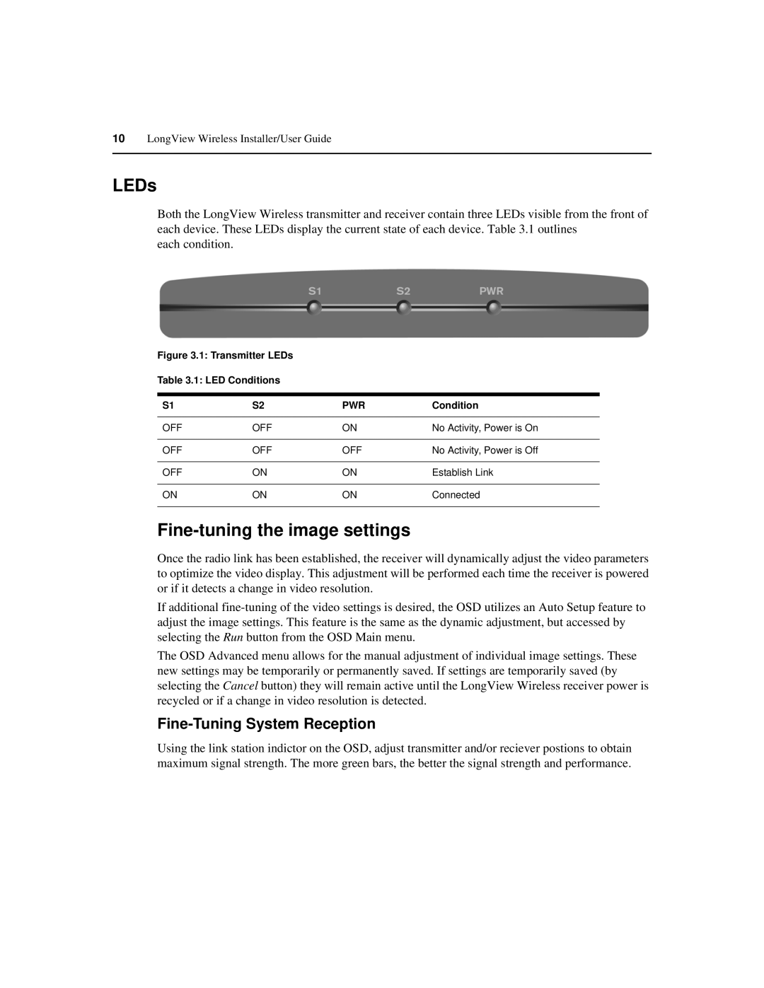
Both the LongView Wireless transmitter and receiver contain three LEDs visible from the front of each device. These LEDs display the current state of each device. Table 3.1 outlines
each condition.
Figure 3.1: Transmitter LEDs
Table 3.1: LED Conditions
S1 | S2 | PWR | Condition |
|
|
|
|
OFF | OFF | ON | No Activity, Power is On |
|
|
|
|
OFF | OFF | OFF | No Activity, Power is Off |
|
|
|
|
OFF | ON | ON | Establish Link |
|
|
|
|
ON | ON | ON | Connected |
|
|
|
|
Fine-tuning the image settings
Once the radio link has been established, the receiver will dynamically adjust the video parameters to optimize the video display. This adjustment will be performed each time the receiver is powered or if it detects a change in video resolution.
If additional
The OSD Advanced menu allows for the manual adjustment of individual image settings. These new settings may be temporarily or permanently saved. If settings are temporarily saved (by selecting the Cancel button) they will remain active until the LongView Wireless receiver power is recycled or if a change in video resolution is detected.
Fine-Tuning System Reception
Using the link station indictor on the OSD, adjust transmitter and/or reciever postions to obtain maximum signal strength. The more green bars, the better the signal strength and performance.
