AXIS M1034-W Network Camera
Technical Specifications
Function/group | Item | Specifications |
|
|
|
| Operating | 0 ºC to 40 ºC (32 ºF to 104 ºF) |
| conditions | Humidity |
| Approvals | EN |
|
| EN 55022 Class B, EN |
|
| EN 55024 |
|
| EN 62311:2008, EN 300 328 |
|
| FCC Part 15 Subpart B and C Class B, VCCI Class B, |
|
| |
|
| EN |
|
| SRRC, ANATEL, TELEC, |
|
| EN/IEC 62741 (risk group 1) |
|
| Power supply: EN |
| Dimensions | 34 mm x 59 mm x 95 mm (1.3” x 2.3” x 3.7”) |
| (HxWxD) |
|
| Weight | Camera: 0.118 kg (0.26 lb.) |
| Included | Power supply, stand and clamp, extension for stand 100 mm (4.0”), Quick Guide, |
| accessories | Installation and Management Software CD, Windows decoder |
| Video | AXIS Camera Companion (software included on CD) — Basic surveillance for small |
| management | businesses, where video is recorded to edge storage |
| software | AXIS Camera Station (sold separately) — Fully featured surveillance for |
|
| installations, where video is recorded on a system server For more information and |
|
| software applications from partners, see www.axis.com/products/video/software/ |
| Optional | PoE Active Splitter |
| accessories | Installation Display |
|
| Network I/O Audio Module |
|
|
|
Connectors
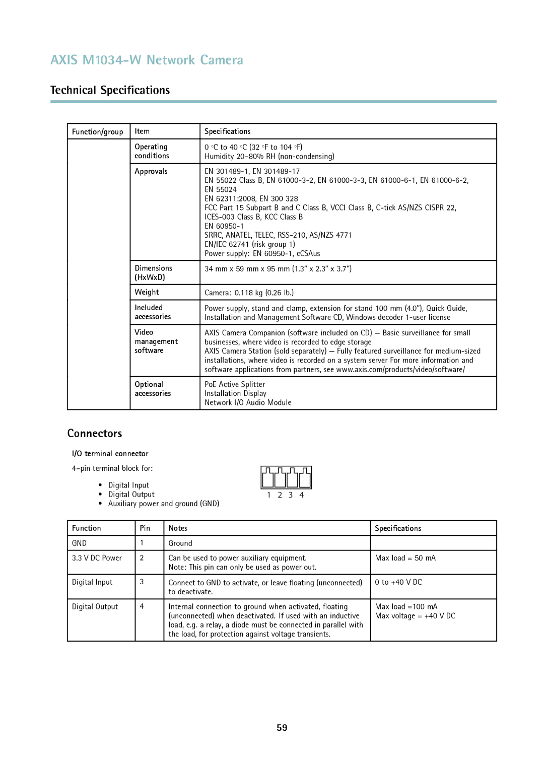
I/O terminal connector |
|
|
|
|
|
|
|
|
|
|
|
|
|
|
|
| ||
|
|
|
|
|
|
|
|
|
|
|
|
|
|
|
| |||
|
|
|
|
|
|
|
|
|
|
|
|
|
|
|
| |||
• | Digital Input |
|
|
|
|
|
|
|
|
|
|
|
|
|
|
|
| |
• | Digital Output | 1 2 3 4 |
|
|
| |||||||||||||
• Auxiliary power and ground (GND) |
| |||||||||||||||||
|
|
|
|
| ||||||||||||||
Function |
| Pin | Notes | Specifications | ||||||||||||||
|
|
|
|
| ||||||||||||||
GND |
| 1 | Ground |
| ||||||||||||||
|
|
|
| |||||||||||||||
3.3 V DC Power | 2 | Can be used to power auxiliary equipment. | Max load = 50 mA | |||||||||||||||
|
|
| Note: This pin can only be used as power out. |
| ||||||||||||||
|
|
|
| |||||||||||||||
Digital Input | 3 | Connect to GND to activate, or leave floating (unconnected) | 0 to +40 V DC | |||||||||||||||
|
|
| to deactivate. |
| ||||||||||||||
|
|
|
| |||||||||||||||
Digital Output | 4 | Internal connection to ground when activated, floating | Max load =100 mA | |||||||||||||||
|
|
| (unconnected) when deactivated. If used with an inductive | Max voltage = +40 V DC | ||||||||||||||
|
|
| load, e.g. a relay, a diode must be connected in parallel with |
| ||||||||||||||
|
|
| the load, for protection against voltage transients. |
| ||||||||||||||
|
|
|
|
|
|
|
|
|
|
|
|
|
|
|
|
|
|
|
59
