Page 24 | AXIS |
Note:
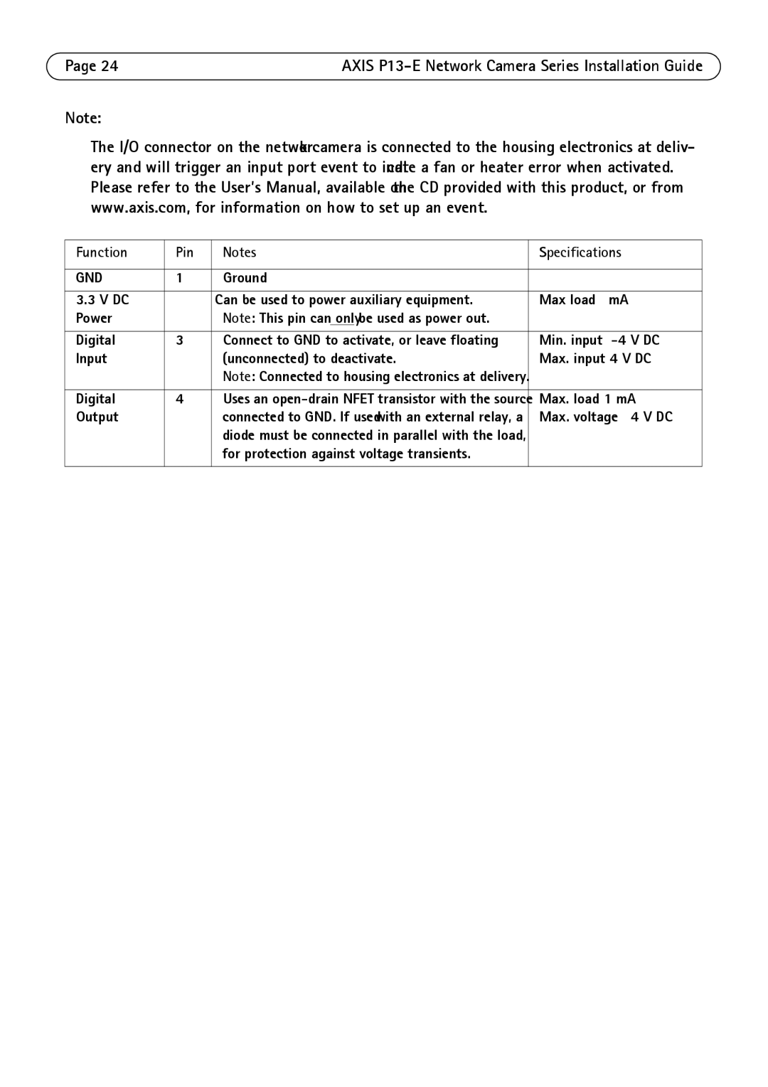
The I/O connector on the network camera is connected to the housing electronics at deliv- ery and will trigger an input port event to indicate a fan or heater error when activated. Please refer to the User’s Manual, available on the CD provided with this product, or from www.axis.com, for information on how to set up an event.
Function | Pin | Notes | Specifications |
|
|
|
|
GND | 1 | Ground |
|
|
|
|
|
3.3 V DC | 2 | Can be used to power auxiliary equipment. | Max load = 50 mA |
Power |
| Note: This pin can only be used as power out. |
|
|
|
|
|
Digital | 3 | Connect to GND to activate, or leave floating | Min. input = |
Input |
| (unconnected) to deactivate. | Max. input= +40 V DC |
|
| Note: Connected to housing electronics at delivery. |
|
|
|
|
|
Digital | 4 | Uses an | Max. load =100 mA |
Output |
| connected to GND. If used with an external relay, a | Max. voltage = + 40 V DC |
|
| diode must be connected in parallel with the load, |
|
|
| for protection against voltage transients. |
|
|
|
|
|