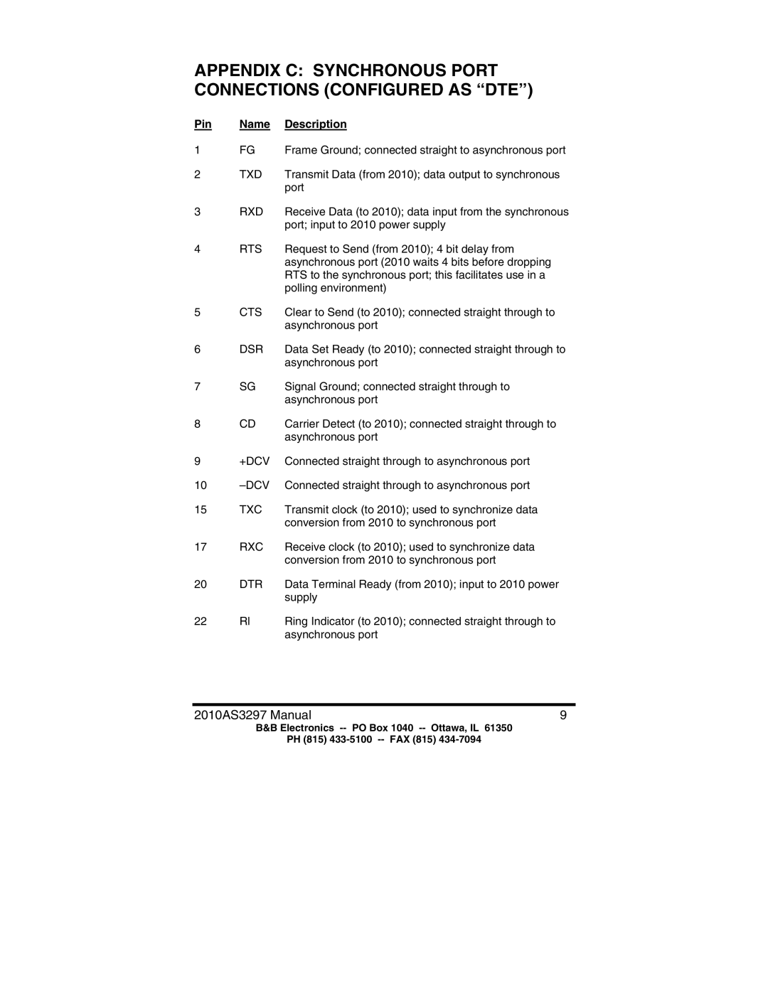
APPENDIX C: SYNCHRONOUS PORT CONNECTIONS (CONFIGURED AS “DTE”)
Pin | Name | Description |
1 | FG | Frame Ground; connected straight to asynchronous port |
2 | TXD | Transmit Data (from 2010); data output to synchronous |
|
| port |
3 | RXD | Receive Data (to 2010); data input from the synchronous |
|
| port; input to 2010 power supply |
4 | RTS | Request to Send (from 2010); 4 bit delay from |
|
| asynchronous port (2010 waits 4 bits before dropping |
|
| RTS to the synchronous port; this facilitates use in a |
|
| polling environment) |
5 | CTS | Clear to Send (to 2010); connected straight through to |
|
| asynchronous port |
6 | DSR | Data Set Ready (to 2010); connected straight through to |
|
| asynchronous port |
7 | SG | Signal Ground; connected straight through to |
|
| asynchronous port |
8 | CD | Carrier Detect (to 2010); connected straight through to |
|
| asynchronous port |
9 | +DCV | Connected straight through to asynchronous port |
10 | Connected straight through to asynchronous port | |
15 | TXC | Transmit clock (to 2010); used to synchronize data |
|
| conversion from 2010 to synchronous port |
17 | RXC | Receive clock (to 2010); used to synchronize data |
|
| conversion from 2010 to synchronous port |
20 | DTR | Data Terminal Ready (from 2010); input to 2010 power |
|
| supply |
22 | Rl | Ring Indicator (to 2010); connected straight through to |
|
| asynchronous port |
2010AS3297 Manual | 9 |
B&B Electronics
PH (815)
