7.6 Pulse Generator Mode
|
|
| 4 |
| 1 |
|
|
|
| ||||
|
|
|
|
|
|
|
|
|
|
|
|
| |
|
|
|
|
|
|
|
|
|
|
|
|
|
|
|
|
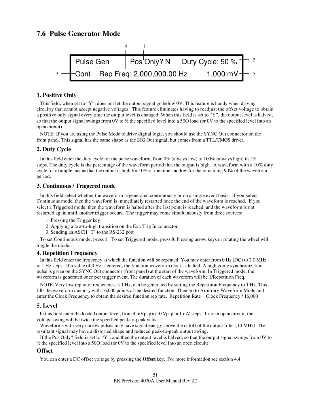
| Pulse Gen |
| Pos |
| Only? N Duty Cycle: 50 % |
|
| ||||
|
|
|
|
| |||||||||
|
|
|
|
|
|
|
|
|
|
| |||
3 |
|
| Cont Rep Freq: 2,000,000.00 Hz | 1,000 mV |
|
| |||||||
|
|
|
| ||||||||||
|
|
|
|
|
|
|
|
|
|
|
|
|
|
2
5
1. Positive Only
This field, when set to “Y”, does not let the output signal go below 0V. This feature is handy when driving circuitry that cannot accept negative voltages. This feature eliminates having to readjust the offset voltage to obtain a positive only signal every time the output level is changed. When this field is set to “Y”, the output level is halved, so that the output signal swings from 0V to ½ the specified level into a 50O load (or 0V to the specified level into an open circuit).
NOTE: If you are using the Pulse Mode to drive digital logic, you should use the SYNC Out connector on the front panel. This signal has the same shape as the SIG Out signal, but comes from a TTL/CMOS driver.
2. Duty Cycle
In this field enter the duty cycle for the pulse waveform, from 0% (always low) to 100% (always high) in 1% steps. The duty cycle is the percentage of the waveform period that the output is high. A waveform with a 10% duty cycle for example means that the output is high for 10% of the time and low for the remaining 90% of the waveform period.
3. Continuous / Triggered mode
In this field select whether the waveform is generated continuously or on a single event basis. If you select Continuous mode, then the waveform is immediately restarted once the end of the waveform is reached. If you select a Triggered mode, then the waveform is halted after the last point is reached, and the waveform is not restarted again until another trigger occurs. The trigger may come simultaneously from three sources:
1.Pressing the Trigger key
2.Applying a
3.Sending an ASCII "T" to the
To set Continuous mode, press 1. To set Triggered mode, press 0. Pressing arrow keys or rotating the wheel will toggle the mode.
4. Repetition Frequency
In this field enter the frequency at which the function will be repeated. You may enter from 0 Hz (DC) to 2.0 MHz in 1 Hz steps. If a value of 0 Hz is entered, the function waveform clock is halted. A high going synchronization pulse is given on the SYNC Out connector (front panel) at the start of the waveform. In Triggered mode, the waveform is generated once per trigger event. The duration of each waveform will be 1/Repetition Freq.
NOTE: Very low rep rate frequencies, < 1 Hz, can be generated by setting the Repetition Frequency to 1 Hz. This fills the waveform memory with 16,000 points of the desired function. Then go to Arbitrary Waveform Mode and enter the Clock Frequency to obtain the desired function rep rate. Repetition Rate = Clock Frequency / 16,000
5. Level
In this field enter the loaded output level, from 4 mVp
Waveforms with very narrow pulses may have signal energy above the cutoff of the output filter (10 MHz). The resultant signal may have a distorted shape and reduced
If the Pos Only? field is set to “Y”, and then the output level is halved, so that the output signal swings from 0V to ½ the specified level into a 50O load (or 0V to the specified level into an open circuit).
Offset
You can enter a DC offset voltage by pressing the Offset key. For more information see section 4.4.
51
BK Precision 4070A User Manual Rev.2.2