5.12 Internal SSB Mode
Introduction
Internal SSB mode generates a Single Sideband modulated signal of fixed carrier frequency. Internally generated signal is used to modulate either Upper sideband or Lower sideband of a carrier signal. Modulating, carrier frequencies and output level with DC offset values could be manually entered on the keypad. External signal gating option is available in this mode. Internal SSB mode could be entered by pressing “Mode”> “SSB” >”1” key at any time.
Internal SSB Mode Parameters
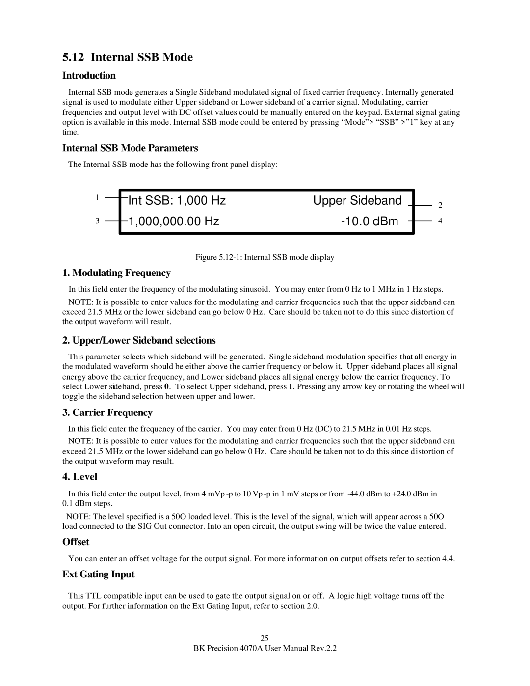
The Internal SSB mode has the following front panel display:
1 |
|
| Int SSB: 1,000 Hz | Upper Sideband |
| |
|
|
| ||||
|
|
|
| |||
|
|
| 1,000,000.00 Hz |
|
|
|
3 |
|
|
|
| ||
|
|
|
| |||
|
|
|
|
|
|
|
Figure 5.12-1: Internal SSB mode display
1. Modulating Frequency
2
4
In this field enter the frequency of the modulating sinusoid. You may enter from 0 Hz to 1 MHz in 1 Hz steps.
NOTE: It is possible to enter values for the modulating and carrier frequencies such that the upper sideband can exceed 21.5 MHz or the lower sideband can go below 0 Hz. Care should be taken not to do this since distortion of the output waveform will result.
2. Upper/Lower Sideband selections
This parameter selects which sideband will be generated. Single sideband modulation specifies that all energy in the modulated waveform should be either above the carrier frequency or below it. Upper sideband places all signal energy above the carrier frequency, and Lower sideband places all signal energy below the carrier frequency. To select Lower sideband, press 0. To select Upper sideband, press 1. Pressing any arrow key or rotating the wheel will toggle the sideband selection between upper and lower.
3. Carrier Frequency
In this field enter the frequency of the carrier. You may enter from 0 Hz (DC) to 21.5 MHz in 0.01 Hz steps. NOTE: It is possible to enter values for the modulating and carrier frequencies such that the upper sideband can
exceed 21.5 MHz or the lower sideband can go below 0 Hz. Care should be taken not to do this since distortion of the output waveform may result.
4. Level
In this field enter the output level, from 4 mVp
NOTE: The level specified is a 50O loaded level. This is the level of the signal, which will appear across a 50O load connected to the SIG Out connector. Into an open circuit, the output swing will be twice the value entered.
Offset
You can enter an offset voltage for the output signal. For more information on output offsets refer to section 4.4.
Ext Gating Input
This TTL compatible input can be used to gate the output signal on or off. A logic high voltage turns off the output. For further information on the Ext Gating Input, refer to section 2.0.
25
BK Precision 4070A User Manual Rev.2.2