Bacharach RDM800, HGM300 SECTION Clipping Fault Adjustment, Section, TP2 TP1 +, R34 - Gain Adjust

Models: HGM300 RDM800

1 21
Download 21 pages 6.66 Kb
Page 10
Image 10
SECTION 5

SECTION 5

Clipping Fault Adjustment

Locate R-34 Gain adjust potentiometer. Adjust DETECTOR voltage using the Diagnostic screen until the voltage is 4.24 volts. If the reference voltage is properly set, the clipping fault will go away after the unit samples the next zone.

Note - It may take several minutes for a voltage change to appear on the diagnostic screen due to the cycle time of the monitor from zone to zone.

If the clipping fault remains, the reference voltage must be verified and corrected if needed.

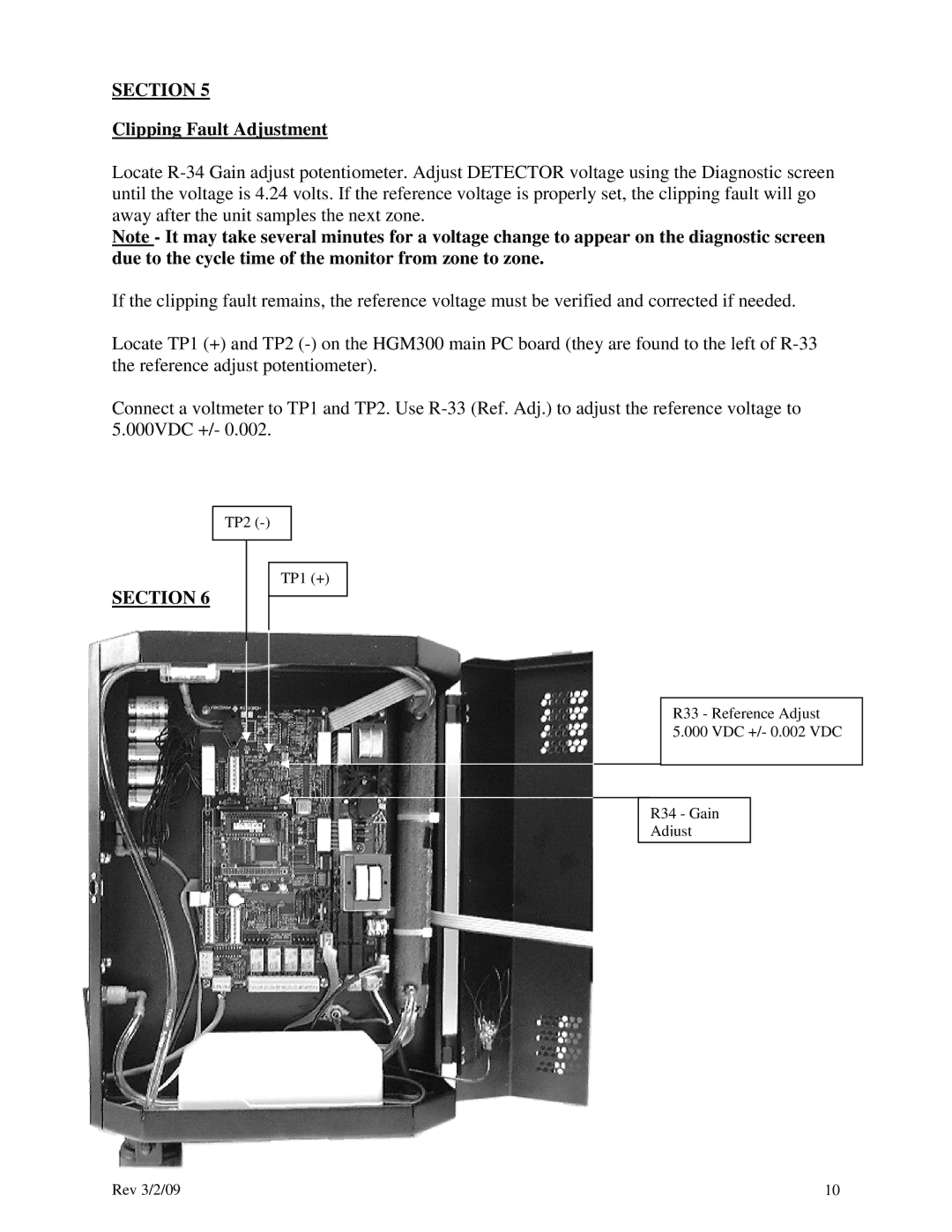
Locate TP1 (+) and TP2 (-) on the HGM300 main PC board (they are found to the left of R-33 the reference adjust potentiometer).

Connect a voltmeter to TP1 and TP2. Use R-33 (Ref. Adj.) to adjust the reference voltage to 5.000VDC +/- 0.002.

TP2 (-)

TP1 (+)

SECTION 6

R33 - Reference Adjust

5.000 VDC +/- 0.002 VDC

R34 - Gain

Adjust

Rev 3/2/09

10

Page 10
Image 10
Bacharach RDM800 SECTION Clipping Fault Adjustment, Section, TP2 TP1 +, R33 - Reference Adjust 5.000 VDC +/- 0.002 VDC