more rapid deceleration time, rotate the DECEL trimpot coun- terclockwise. For longer deceleration time, rotate the DECEL trimpot clockwise. See Figure 20.
Note: To provide increased resolution of the ACCEL and DECEL trimpots, 50% rotation covers 0.3 - 5 seconds.
Application Note: On applications with high inertial loads, the deceleration may automatically increase in time. This will slow down the rate of speed decrease to prevent the bus volt- age from rising to the overvoltage trip point. This function is called regeneration protection. It is recommended that for very high inertial loads that both the ACCEL and DECEL trimpots should not be set to less than ten (10) seconds.
FIGURE 20
DECEL TRIMPOT RANGE
| 5 |
2.5 | 12.5 |
1.5 |
|
0.3 | 20 |
Seconds
(Shown Factory Set to 1.5 Seconds)
FIGURE 21
COMP TRIMPOT RANGE
E. Slip Compensation (COMP) – Sets the amount of |
|
|
| 1.5 |
|
|
|
|
|
|
|
|
| ||||||||
Volts/Hz/Amp to maintain set motor speed under varying | 0.8 |
|
|
|
|
|
|
|
|
|
|
|
|
|
|
|
|
| 2.3 | ||
|
|
|
|
|
|
|
|
|
|
|
|
|
|
|
|
| |||||
loads. The COMP trimpot is factory set for 1.5 Volts/Hz/Amp. |
|
|
|
|
|
|
|
|
|
|
|
|
|
|
|
|
| ||||
|
|
|
|
|
|
|
|
|
|
|
|
|
|
|
|
|
|
| |||
The slip compensation may be adjusted by the COMP trim- |
|
|
|
|
|
|
|
|
|
|
|
|
|
|
|
|
|
|
| ||
pot as described below. See Figure 21. | 0 |
|
|
|
|
|
|
|
|
|
|
|
|
|
|
|
| 3 | |||
|
|
|
|
| |||||||||||||||||
1. | Wire an ammeter in series with one motor phase. |
|
|
|
|
|
|
|
|
|
|
|
|
|
|
|
|
|
|
| |
|
|
|
|
|
| Volts/Hz/Amp | |||||||||||||||
|
|
|
|
|
|
|
| ||||||||||||||
2. | Run the motor and set the unloaded speed to approxi- | Shown Factory Set to 1.5 Volts/Hz/Amp | |||||||||||||||||||
|
|
|
|
|
|
|
|
|
|
|
|
|
|
|
|
|
|
| |||
| mately 50%. |
|
|
|
|
|
|
|
|
|
|
|
|
|
|
|
|
|
|
| |
|
|
|
|
|
|
|
|
| |||||||||||||
3. | Load the motor to the rated motor nameplate current |
|
|
|
|
|
| FIGURE 22 | |||||||||||||
CL TRIMPOT RANGE | |||||||||||||||||||||
| (Amps AC). | ||||||||||||||||||||
|
|
|
|
|
|
|
|
|
|
|
|
|
|
|
|
|
|
|
| ||
4. | Adjust the COMP trimpot so that the loaded RPM is equal |
|
|
| 120 |
|
|
|
|
|
|
|
| ||||||||
|
|
|
|
|
|
|
|
|
|
|
|
|
|
|
|
|
|
| |||
| to the unloaded RPM. | 80 |
|
|
|
|
|
|
|
|
|
|
| 160 | |||||||
|
|
|
|
| |||||||||||||||||
5. | The motor is now compensated to provide constant |
|
|
|
|
|
|
|
|
|
|
|
|
|
|
|
|
|
|
| |
| speed under varying loads. | 40 |
|
|
|
|
|
|
|
|
| 200 | |||||||||
|
|
|
|
| |||||||||||||||||
F. Current Limit with I2t Shutdown (CL) – Sets the current | Percent of Range Setting | ||||||||||||||||||||
limit (overload), which limits the maximum current to the | |||||||||||||||||||||
(Shown Factory Set to 160%) | |||||||||||||||||||||
motor. The current limit set point is established by the setting |
|
|
|
|
|
|
|
|
|
|
|
|
|
|
|
|
|
|
| ||
of Jumper J3 and the setting of the CL trimpot. See Figure 22. |
|
|
|
|
|
|
|
|
|
|
|
|
|
|
|
| |||||
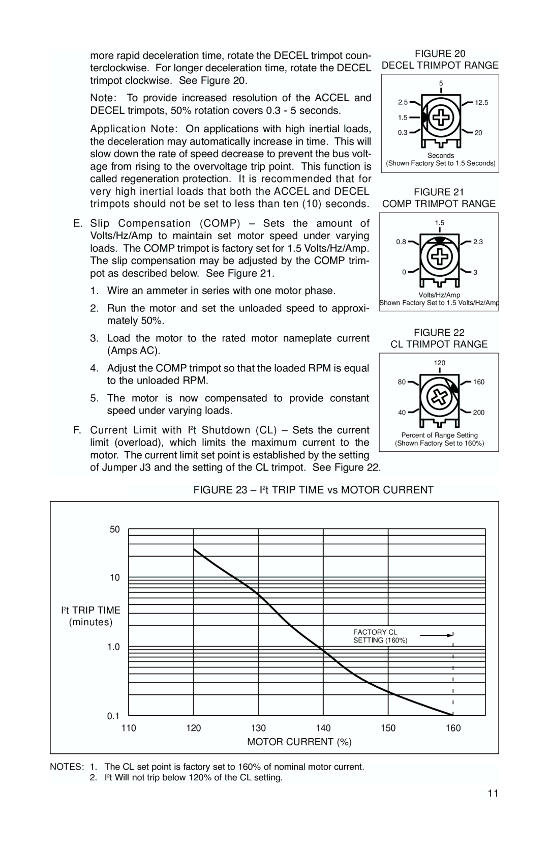
FIGURE 23 – I2t TRIP TIME vs MOTOR CURRENT
50 |
|
|
|
|
|
10 |
|
|
|
|
|
I2t TRIP TIME |
|
|
|
|
|
(minutes) |
|
|
|
|
|
|
|
|
| FACTORY CL |
|
1.0 |
|
|
| SETTING (160%) |
|
|
|
|
|
| |
0.1 |
|
|
|
|
|
110 | 120 | 130 | 140 | 150 | 160 |
|
| MOTOR CURRENT (%) |
|
| |
NOTES: 1. The CL set point is factory set to 160% of nominal motor current. 2. I2t Will not trip below 120% of the CL setting.
11
