24 Eco HE specifications
The Baxi Potterton 24 Eco HE is a highly efficient and reliable boiler designed to meet the heating and hot water needs of modern homes. This wall-mounted combination boiler is particularly suited for smaller properties, providing a compact solution without compromising on performance.One of the standout features of the Baxi Potterton 24 Eco HE is its high efficiency rating. It boasts an impressive ErP A-rating for both heating and hot water, which indicates that it is designed to minimize energy consumption and reduce utility bills. The condensing technology employed in this boiler recovers heat from flue gases that would otherwise be lost, optimizing the overall energy use and enhancing its eco-friendly credentials.
The Baxi Potterton 24 Eco HE also incorporates an intelligent control system, allowing homeowners to manage their heating settings more effectively. The built-in digital display is user-friendly, providing easy access to information such as system pressure and temperature settings. This feature facilitates easy programming of heating schedules, helping to ensure comfort while optimizing energy use.
Another characteristic of the Baxi Potterton 24 Eco HE is its impressive hot water output. With a hot water flow rate of up to 10.2 liters per minute, it ensures that showers and taps can be used simultaneously without running out of hot water. This makes it an excellent choice for families or households where demand for hot water is high.
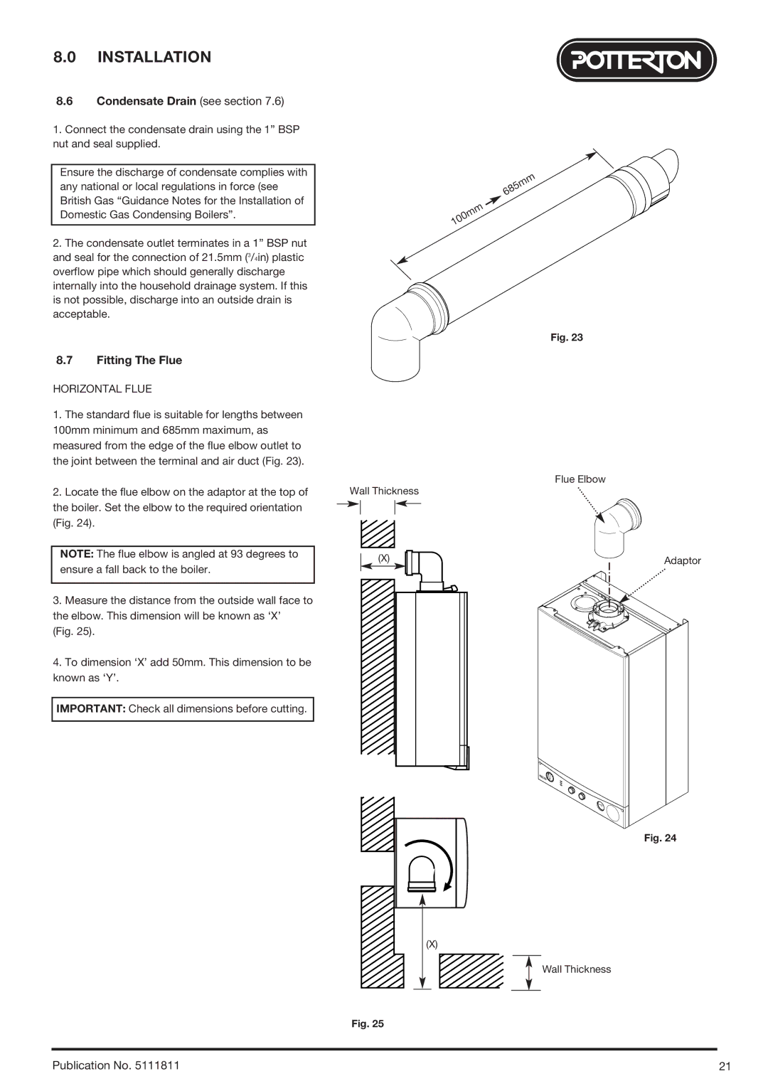
Furthermore, the compact design of the Baxi Potterton 24 Eco HE allows for flexible installation options. Its reduced size means it can fit easily in kitchen cupboards or other confined spaces, making it ideal for homes where space is at a premium.
The boiler is equipped with a low-energy pump and a built-in frost protection feature, ensuring reliable operation even in colder climates. Additionally, its quiet operation contributes to a more comfortable living environment.
In summary, the Baxi Potterton 24 Eco HE is an efficient, compact, and powerful boiler that caters to the demands of modern living. With features such as high efficiency, intelligent controls, impressive hot water delivery, and flexible installation options, it stands out as a top choice for homeowners seeking a dependable and eco-friendly heating solution. This boiler is a testament to Baxi's commitment to delivering quality and innovation in the heating sector.

