Section: Burner Controls
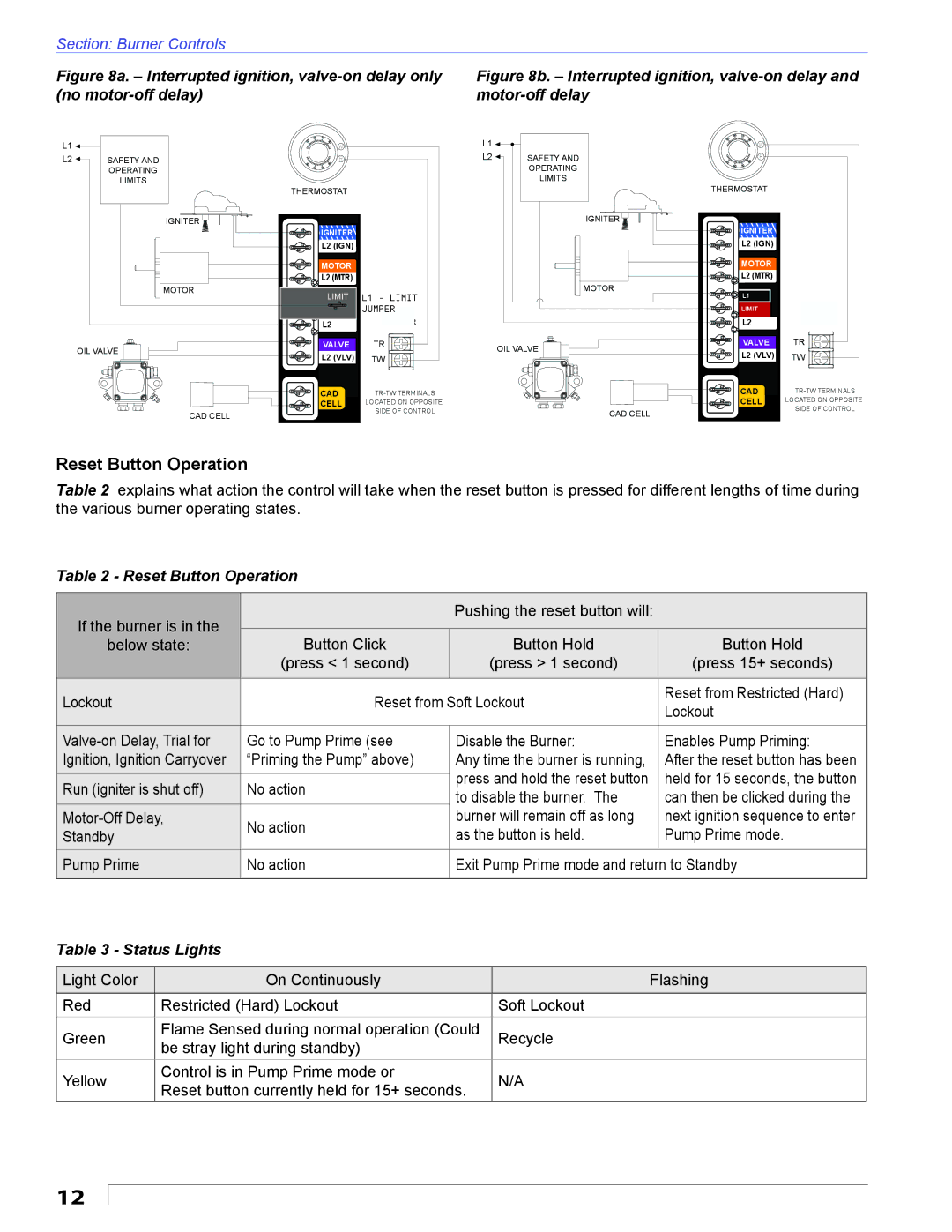
Figure 8a. – Interrupted ignition, valve-on delay only (no motor-off delay)
Figure 8b. – Interrupted ignition, valve-on delay and motor-off delay
L1 ![]()
L2 |
| SAFETY AND |
| ||
|
| OPERATING |
|
| LIMITS |
IGNITER
MOTOR
OIL VALVE
60 | 70 | L1 |
|
50 | W |
| |
80 |
|
| |
| R | L2 | SAFETY AND |
50 | 80 |
| OPERATING |
60 | 70 |
| |
|
|
| LIMITS |
THERMOSTAT |
|
| |
|
|
| IGNITER |
| IGNITER |
|
|
| L2 (IGN) |
|
|
| MOTOR |
|
|
| L2 (MTR) |
| MOTOR |
| L1LIMIT | L1 - LIMIT | |
|
| ||
| LIMIT | JUMPER |
|
| L2 |
|
|
| VALVE | TR | OIL VALVE |
| L2 (VLV) | TW | |
|
| ||
60 | 70 |
|
50 | 80 |
|
| W |
|
| R |
|
50 | 80 |
|
60 | 70 |
|
THERMOSTAT |
| |
| IGNITER |
|
| L2 (IGN) |
|
| MOTOR |
|
| L2 (MTR) |
|
| L1 |
|
| LIMIT | |
| L2 | JUMPER |
| VALVE | TR |
| L2 (VLV) | TW |
CAD |
| |
CELL | LOCATED ON OPPOSITE |
|
CAD CELL | SIDE OF CONTROL | CAD CELL |
|
CAD | |
CELL | LOCATED ON OPPOSITE |
| SIDE OF CONTROL |
Reset Button Operation
Table 2 explains what action the control will take when the reset button is pressed for different lengths of time during the various burner operating states.
Table 2 - Reset Button Operation
If the burner is in the |
| Pushing the reset button will: |
| |
|
|
| ||
Button Click | Button Hold | Button Hold | ||
below state: | ||||
| (press < 1 second) | (press > 1 second) | (press 15+ seconds) | |
Lockout | Reset from Soft Lockout | Reset from Restricted (Hard) | ||
Lockout | ||||
|
|
| ||
|
|
|
| |
Go to Pump Prime (see | Disable the Burner: | Enables Pump Priming: | ||
Ignition, Ignition Carryover | “Priming the Pump” above) | Any time the burner is running, | After the reset button has been | |
|
| press and hold the reset button | held for 15 seconds, the button | |
Run (igniter is shut off) | No action | |||
to disable the burner. The | can then be clicked during the | |||
|
| |||
No action | burner will remain off as long | next ignition sequence to enter | ||
Standby | as the button is held. | Pump Prime mode. | ||
| ||||
|
|
|
| |
Pump Prime | No action | Exit Pump Prime mode and return to Standby | ||
|
|
|
| |
Table 3 - Status Lights
Light Color | On Continuously | Flashing | |
|
|
| |
Red | Restricted (Hard) Lockout | Soft Lockout | |
Green | Flame Sensed during normal operation (Could | Recycle | |
be stray light during standby) | |||
|
| ||
Yellow | Control is in Pump Prime mode or | N/A | |
Reset button currently held for 15+ seconds. | |||
|
|
12
