Mount Burner on Appliance
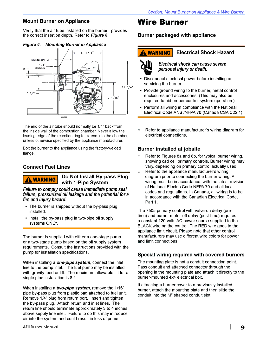
Verify that the air tube installed on the burner provides the correct insertion depth. Refer to Figure 6.
Figure 6. – Mounting Burner in Appliance
Beckett
3 GPH
The end of the air tube should normally be 1/4” back from the inside wall of the combustion chamber. Never allow the leading edge of the retention ring to extend into the chamber, unless otherwise specified by the appliance manufacturer.
Bolt the burner to the appliance using the
Connect Fuel Lines
Do Not Install
Failure to comply could cause Immediate pump seal failure, pressurized oil leakage and the potential for a fire and injury hazard.
yThe burner is shipped without the
yInstall the
The burner is supplied with either a
When installing a
When installing a
Section: Mount Burner on Appliance & Wire Burner
Wire Burner
Burner packaged with appliance
 Electrical Shock Hazard
Electrical shock can cause severe personal injury or death.
yDisconnect electrical power before installing or servicing the burner.
yProvide ground wiring to the burner, metal control enclosures and accessories. (This may also be required to aid proper control system operation.)
yPerform all wiring in compliance with the National Electrical Code ANSI/NFPA 70 (Canada CSA C22.1)
○Refer to appliance manufacturer’s wiring diagram for electrical connections.
Burner installed at jobsite
○Refer to Figures 8a and 8b, for typical burner wiring, showing cad cell primary controls. Burner wiring may vary, depending on primary control actually used.
○Refer to the appliance manufacturer’s wiring diagram prior to connecting the burner wiring. All wiring must be in accordance with the latest revision of National Electric Code NFPA 70 and all local codes and regulations. In Canada, all wiring is to be in accordance with the Canadian Electrical Code, Part 1.
The 7505 primary control with
Special wiring required with covered burners
The mounting plate is not a conduit connection point. Pass conduit and attached connector through the opening in the mounting plate and attach it directly to the
If attaching a burner cover to a previously installed burner, attach the mounting plate and then slide the conduit into the “J” shaped conduit slot.
AFII Burner Manual
9