Section: Prepare the Burner
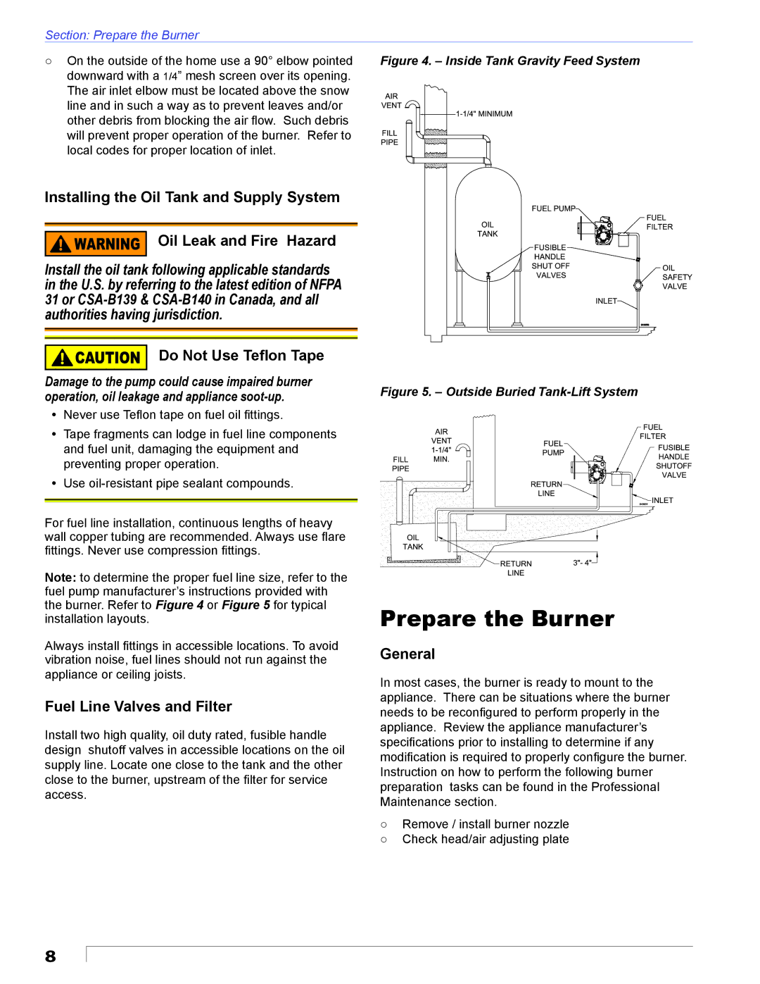
○ On the outside of the home use a 90° elbow pointed | Figure 4. – Inside Tank Gravity Feed System |
downward with a 1/4” mesh screen over its opening. |
|
The air inlet elbow must be located above the snow |
|
line and in such a way as to prevent leaves and/or |
|
other debris from blocking the air flow. Such debris |
|
will prevent proper operation of the burner. Refer to |
|
local codes for proper location of inlet. |
|
Installing the Oil Tank and Supply System |
|
Oil Leak and Fire Hazard |
|
Install the oil tank following applicable standards |
|
in the U.S. by referring to the latest edition of NFPA |
|
31 or |
|
authorities having jurisdiction. |
|
Do Not Use Teflon Tape |
|
Damage to the pump could cause impaired burner | Figure 5. – Outside Buried |
operation, oil leakage and appliance |
yNever use Teflon tape on fuel oil fittings.
yTape fragments can lodge in fuel line components and fuel unit, damaging the equipment and preventing proper operation.
yUse
For fuel line installation, continuous lengths of heavy wall copper tubing are recommended. Always use flare fittings. Never use compression fittings.
Note: to determine the proper fuel line size, refer to the fuel pump manufacturer’s instructions provided with the burner. Refer to Figure 4 or Figure 5 for typical installation layouts.
Always install fittings in accessible locations. To avoid vibration noise, fuel lines should not run against the appliance or ceiling joists.
Fuel Line Valves and Filter
Install two high quality, oil duty rated, fusible handle design shutoff valves in accessible locations on the oil supply line. Locate one close to the tank and the other close to the burner, upstream of the filter for service access.
Prepare the Burner
General
In most cases, the burner is ready to mount to the appliance. There can be situations where the burner needs to be reconfigured to perform properly in the appliance. Review the appliance manufacturer’s specifications prior to installing to determine if any modification is required to properly configure the burner. Instruction on how to perform the following burner preparation tasks can be found in the Professional Maintenance section.
○Remove / install burner nozzle
○Check head/air adjusting plate
8