FS210LS 10 Table SAW
General Safety Rules
Safety Guidelines Definitions
Important Safety Instructions
Failure to Follow These Rules MAY Result in Serious Injury
Stay ALERT, Watch What YOU are DOING,
Additional Safety Rules for Table Saws
Motor Specifications
Power Connections
Grounding Instructions
Functional Description
Extension Cords
Foreword
Unpacking and Cleaning
Assembly
Assembly Tools Required
Assembly Time Estimate
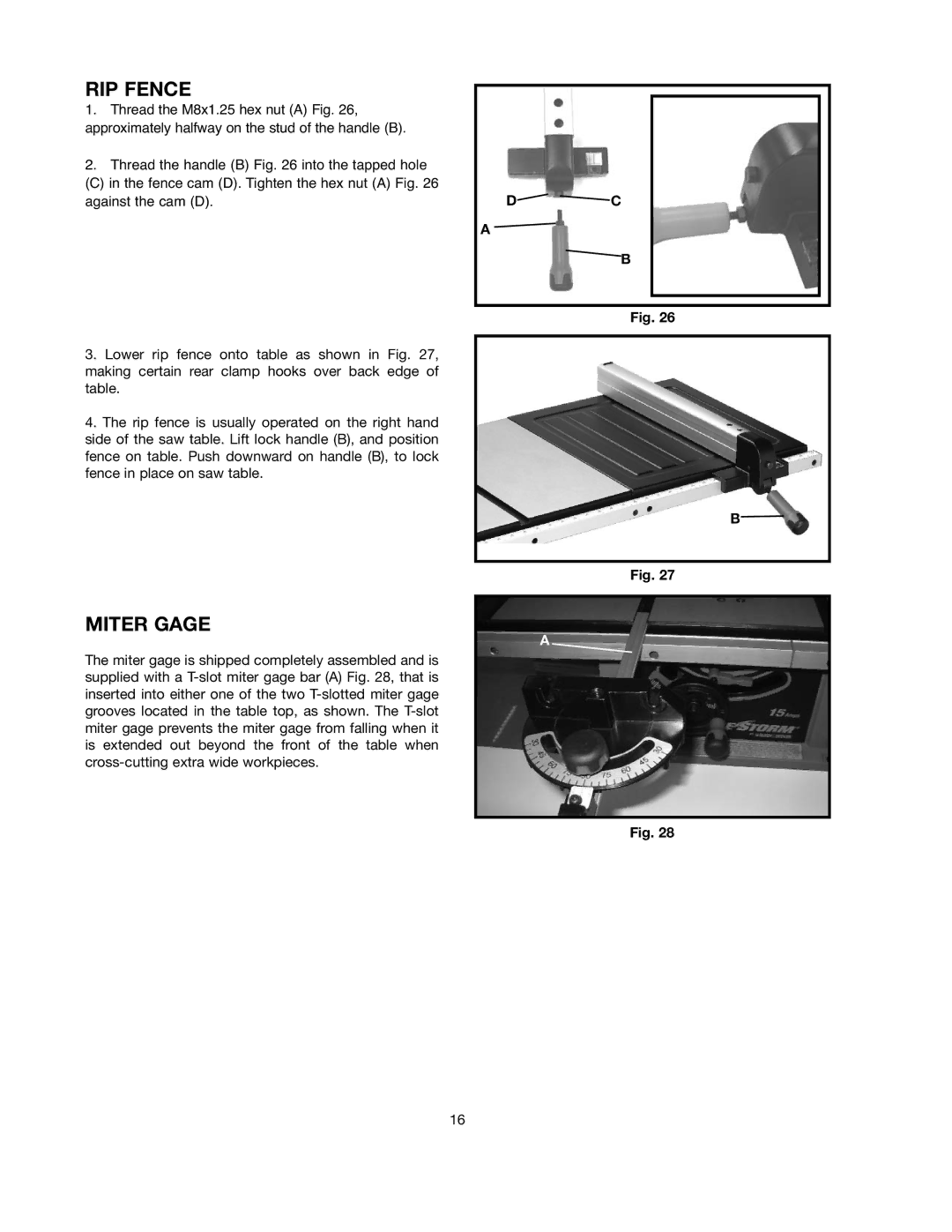
RIP Fence Parts 11,12
Miter Gage Holder Parts 19,20,21,22,23,24,25
Stand Parts
Disconnect Machine from Power Source
Miter Gage Holder
Stand Assembly
Attaching Dust BAG
SAW to Stand
EB D
Assembling Blade Raising and Lowering Handwheel
Blade Guard Splitter Assembly
At this time
Page
Extension Wings
Guide Rail to SAW
RIP Fence
Miter Gage
Outfeed Support
Operating Controls and Adjustments
Locking Switch in the OFF Position
Starting and Stopping SAW
Blade Raising Lowering Control
Adjusting 90 and 45 Degree Positive Stops
To Adjust Positive Stop AT 90 Degrees
To Adjust Positive Stop AT 45 Degrees
Blade Tilting Control
Miter Gage Operation and Adjustments
RIP Fence Operation Adjustments
C BD
Adjusting Blade Parallel to Miter Gage Slots
Changing the Blade
Common Sawing Operations
Never USE the Fence AS a CUT-OFF Gage When CROSS-CUTTING
CROSS-CUTTING
Ripping
Constructing a Push Stick
Using Auxiliary Woodfacing on RIP Fence
Accessory Dado Cutterhead
Attach the dado head set D , to the saw arbor
Constructing a Featherboard
Troubleshooting Guide
WHAT’S WRONG? What to DO…
Push Stick
Constructing a Push Stick
Accessories
Scie À Table DE 254 MM
Règles Générales DE Sécurité
Lignes Directrices EN Matière DE Sécurité Définitions
Directives DE Sécurité Importantes
Retirer LES Clés ET LES Clés DE Réglage
Règles DE Sécurité Supplémentaires Pour LES Scies DE Table
Pour Éviter L’EFFET DE Rebond
Caractéristiques Techniques DU Moteur
Connexions Électriques
Directives DE Mise À LA Terre
Description Fonctionnelle
Rallonges
AVANT-PROPOS
Désemballage ET Nettoyage
Assemblage
Outils Nécessaires Pour L’ASSEMBLAGE
Durée Estimée Pour L’ASSEMBLAGE
Pièce DU Guide Longitudinal 11,12
Pièces DU Volant DE Relèvement DE LA Lame
Pièces DU PORTE-GUIDE D’ONGLET
Pièces DES Barres DE Guidage DU Guide
Pièces DU Socle
PORTE-GUIDE D’ONGLET
Assemblage DU Socle
Raccord DU SAC À Poussière
Fixation DE LA Scie SUR LE Socle
Ensemble DE PROTÈGE-LAME ET Couteau Séparateur
Rallonges
Utilisation DES Commandes ET Réglages
Commande D’ABAISSEMENT ET DE Relèvement DE LA Lame
Commande D’INCLINAISON DE LA Lame
Verrouiller L’INTERRUPTEUR EN Position D’ARRÊT
Réglages DES Butées Positives À 90 ET 45 Degrés
Utilisation ET Réglage DU Guide Longitudinal
Réglage D’UNE Butée Fixe À 45 Degrés
Utilisation ET Réglages DU Guide D’ONGLET
Opérations Courantes DE Sciage
Changement DE LA Lame
Tronçonnage
Débrancher L’APPAREIL DE LA Source D’ALIMENTATION
Fraise Accessoire À Rainurer
Sciage EN Long
Construction D’UNE Planche EN Éventail
Guide DE Dépannage
Suivre LES Règles ET Consignes DE Sécurité
« Fabrication DUN Poussoir »
Accessoires
Sierra DE Mesa FS210LS
Conserve Este Manual Para Futuras Consultas
Normas Generales DE Seguridad
Definiciones DE LAS Normas DE Seguridad
Instrucciones Importantes Sobre Seguridad
Normas Generales DE Seguridad
Normas DE Seguridad Adicionales Para LAS Sierras DE Mesa
Guarde Estas Instrucciones
Conexiones Eléctricas
Descripción DE LAS Funciones
Cables Prolongadores
Introducción
Desembalaje Y Limpieza
Ensamblaje
Herramientas Necesarias Para EL Ensamblaje
Tiempo Aproximado Para EL Ensamblaje
Partes DE LA Guía DE Corte Longitudinal
Partes DEL Volante Para Elevar LA Hoja
Partes DEL Sujetador DEL Calibrador DE
Partes DEL Soporte DE Avance DE Salida
Sujetador DEL Calibrador DE Inglete
Partes DE LA Base
Desconecte LA Máquina DE LA Fuente DE Energía
Ensamblaje DE LA Base
Inserción DE LA Bolsa Recolectora DE Polvo
Sierra a LA Base
Ensamblado DE LA Hoja Volante Para Elevar Y Bajar
Bases DE Extensión
Riel DE Guía a LA Sierra
Controles DE Operación Y Ajustes
Control DE Elevación Y Descenso DE LA Hoja
Control DE Inclinación DE LA Hoja
Ajuste DE Topes Positivos a 90 Y 45 Grados
Ajustar UN Tope Positivo a 90 Grados
Ajustes Y Operación DEL Calibrador DE Inglete
Cambio DE LA Hoja
Operaciones MÁS Comunes DE Corte CON Sierra
Corte Transversal
Corte Longitudinal
Empujar
Cabezal Portacuchilla Accesorio Para Ranuras
Guía DE Detección DE Problemas
Construcción DE UNA Tabla DE Canto Biselado
Vara DE Empuje
Construcción DE UNA Vara Para Empujar
Accesorios