Chapter 2: Overview
Table
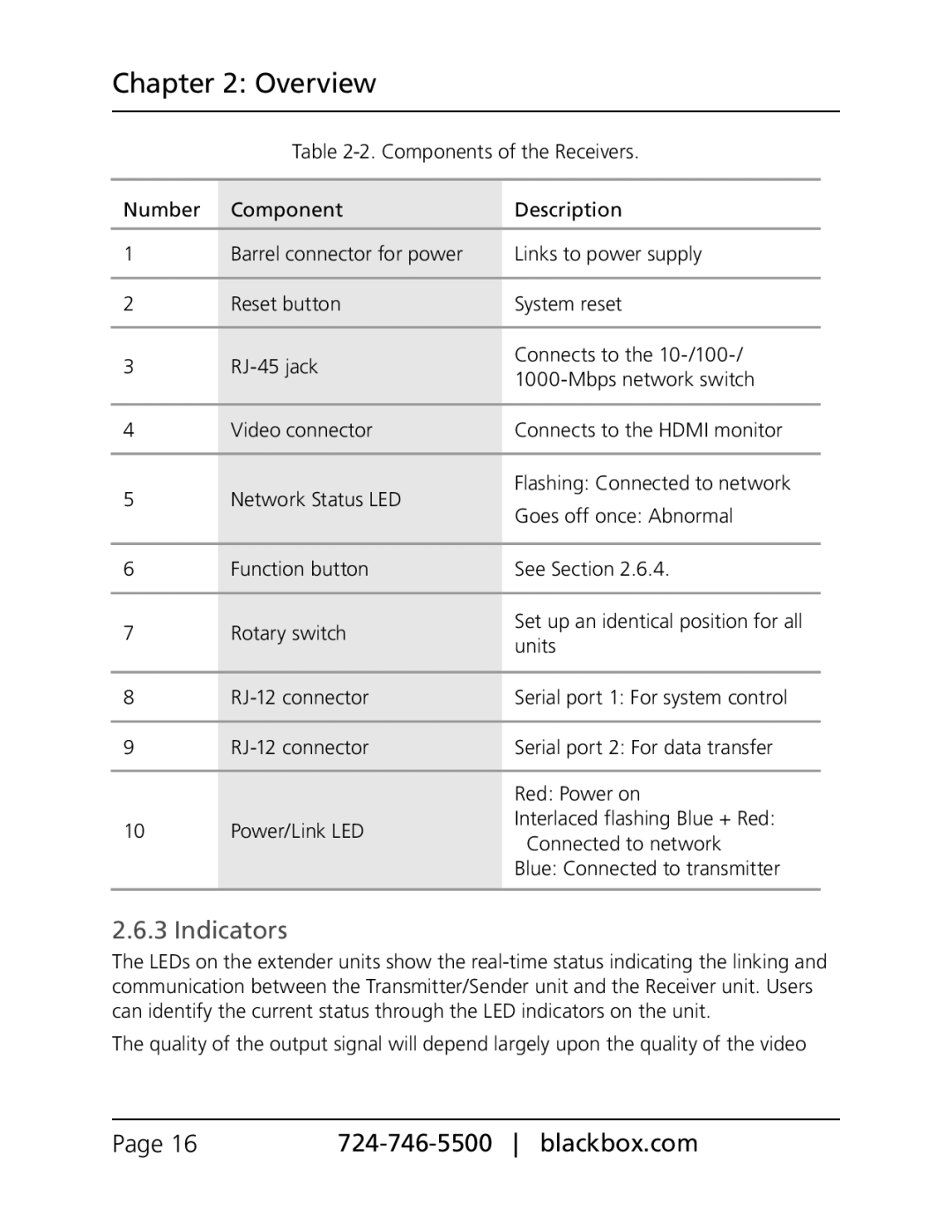
Number | Component | Description | |
|
|
| |
1 | Barrel connector for power | Links to power supply | |
|
|
| |
2 | Reset button | System reset | |
|
|
| |
3 | Connects to the | ||
|
| ||
|
|
| |
4 | Video connector | Connects to the HDMI monitor | |
|
|
| |
5 | Network Status LED | Flashing: Connected to network | |
Goes off once: Abnormal | |||
|
| ||
|
|
| |
6 | Function button | See Section 2.6.4. | |
|
|
| |
7 | Rotary switch | Set up an identical position for all | |
units | |||
|
| ||
|
|
| |
8 | Serial port 1: For system control | ||
|
|
| |
9 | Serial port 2: For data transfer | ||
|
|
| |
|
| Red: Power on | |
10 | Power/Link LED | Interlaced flashing Blue + Red: | |
Connected to network | |||
|
|
Blue: Connected to transmitter
2.6.3 Indicators
The LEDs on the extender units show the
The quality of the output signal will depend largely upon the quality of the video
Page 16 |