Chapter 3: Installation
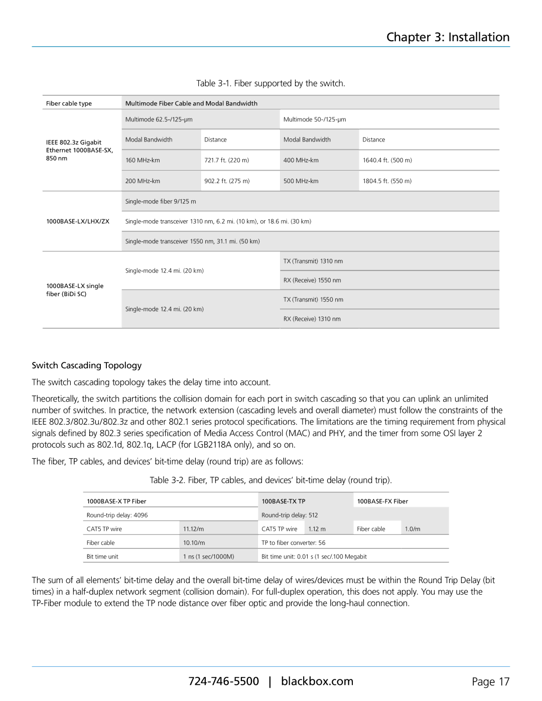
Table 3-1. Fiber supported by the switch.
Fiber cable type | Multimode Fiber Cable and Modal Bandwidth |
|
| |
|
|
|
|
|
| Multimode |
| Multimode |
|
|
|
|
|
|
IEEE 802.3z Gigabit | Modal Bandwidth | Distance | Modal Bandwidth | Distance |
|
|
|
| |
Ethernet |
|
|
|
|
|
|
|
| |
850 nm | 160 | 721.7 ft. (220 m) | 400 | 1640.4 ft. (500 m) |
| ||||
|
|
|
|
|
| 200 | 902.2 ft. (275 m) | 500 | 1804.5 ft. (550 m) |
|
|
|
|
|
|
|
|
| |
TX (Transmit) 1310 nm
RX (Receive) 1550 nm
TX (Transmit) 1550 nm
RX (Receive) 1310 nm
Switch Cascading Topology
The switch cascading topology takes the delay time into account.
Theoretically, the switch partitions the collision domain for each port in switch cascading so that you can uplink an unlimited number of switches. In practice, the network extension (cascading levels and overall diameter) must follow the constraints of the IEEE 802.3/802.3u/802.3z and other 802.1 series protocol specifications. The limitations are the timing requirement from physical signals defined by 802.3 series specification of Media Access Control (MAC) and PHY, and the timer from some OSI layer 2 protocols such as 802.1d, 802.1q, LACP (for LGB2118A only), and so on.
The fiber, TP cables, and devices’
Table
|
|
| |||
|
|
|
|
| |
|
|
| |||
|
|
|
|
|
|
CAT5 TP wire | 11.12/m | CAT5 TP wire | 1.12 m | Fiber cable | 1.0/m |
|
|
|
|
| |
Fiber cable | 10.10/m | TP to fiber converter: 56 |
|
| |
|
|
|
| ||
Bit time unit | 1 ns (1 sec/1000M) | Bit time unit: 0.01 s (1 sec/.100 Megabit |
| ||
|
|
|
|
|
|
The sum of all elements’
Page 17 |
