Chapter 4: Installation
4. Installation
This chapter gives
4.1 Selecting a Site for the Equipment
As with any electric device, you should place the equipment where it will not be subjected to extreme temperatures, humidity, or electromagnetic interference. Specifically, the site you select should meet the following requirements:
•The surrounding air temperature should be between
•The relative humidity should be less than 95 percent, noncondensing.
•Surrounding electrical devices should not exceed the electromagnetic field (RFC) standards.
•Make sure that the equipment receives adequate ventilation. Do not block the ventilation holes of the equipment.
•The power outlet should be within 6 feet (1.8 meters) of the product.
4.2 Wiring Diagram
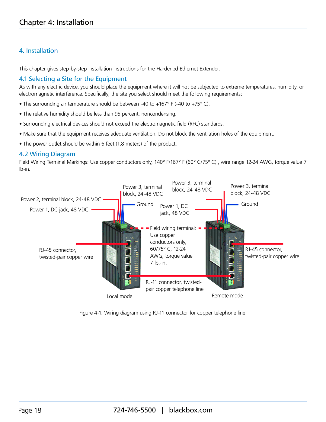
Field Wiring Terminal Markings: Use copper conductors only, 140° F/167° F (60° C/75° C) , wire range
|
|
|
| Power 3, terminal | Power 3, terminal |
| Power 3, terminal | |||||||
|
|
|
| block, | ||||||||||
|
|
|
| block, | block, | |||||||||
Power 2, terminal block, |
|
|
|
| ||||||||||
|
|
| Ground |
|
|
|
|
|
| Ground | ||||
Power 1, DC jack, 48 VDC |
|
|
|
| Power 1, DC |
|
|
|
| |||||
|
|
|
|
|
|
|
|
|
| |||||
|
|
|
|
| jack, 48 VDC |
|
|
|
|
| ||||
|
|
|
|
|
|
|
|
|
|
|
| |||
|
|
|
|
|
| Field wiring terminal: |
|
|
|
|
| |||
|
|
|
|
|
|
|
|
|
|
| ||||
|
|
|
|
|
| Use copper |
|
|
|
|
| |||
|
|
|
|
|
| conductors only, |
|
|
|
|
| |||
|
|
| 60/75° C, |
|
|
| ||||||||
|
|
| AWG, torque value |
|
|
| ||||||||
|
|
|
|
|
| 7 |
|
|
|
|
|
|
| |
|
|
|
|
|
|
|
|
|
|
|
|
| ||
|
|
|
|
|
|
|
|
|
|
| ||||
|
|
|
|
|
| pair copper telephone line |
|
|
|
|
| |||
|
|
| Local mode |
|
|
| Remote mode | |||||||
Figure 4-1. Wiring diagram using RJ-11 connector for copper telephone line.
Page 18 |