Quick Start Guide
•PoE LED is only on the for Hardened IEEE 802.3at PoE PSE Ethernet Extender versions (LBPS301A and LBPS304A).
•DC Terminal Block Power Inputs: There are two pairs of power inputs that you can use to power up this Ethernet Extender.
Redundant power supplies function is supported. You only need to have one power input connected to run the Ethernet Extender.
•DC jack: Power Input: 48 VDC.
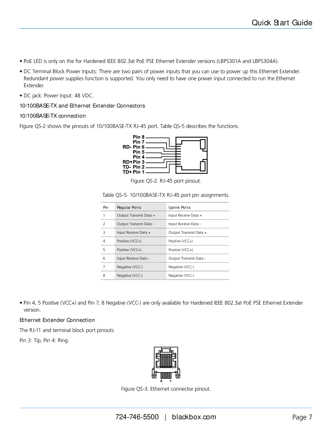
Figure QS-2 shows the pinouts of 10/100BASE-TX RJ-45 port. Table QS-5 describes the functions.
Figure QS-2. RJ-45 port pinout.
Table QS-5. 10/100BASE-TX RJ-45 port pin assignments.
Pin | Regular Ports | Uplink Ports |
|
|
|
1 | Output Transmit Data + | Input Receive Data + |
|
|
|
2 | Output Transmit Data - | Input Receive Data - |
|
|
|
3 | Input Receive Data + | Output Transmit Data + |
|
|
|
4 | Positive (VCC+) | Positive (VCC+) |
|
|
|
5 | Positive (VCC+) | Positive (VCC+) |
|
|
|
6 | Input Receive Data - | Output Transmit Data - |
|
|
|
7 | Negative | Negative |
|
|
|
8 | Negative | Negative |
|
|
|
•Pin 4, 5 Positive (VCC+) and Pin 7, 8 Negative
Ethernet Extender Connection
The
Pin 3: Tip, Pin 4: Ring.
Figure QS-3. Ethernet connector pinout.
Page 7 |