Chapter 3: Configuration
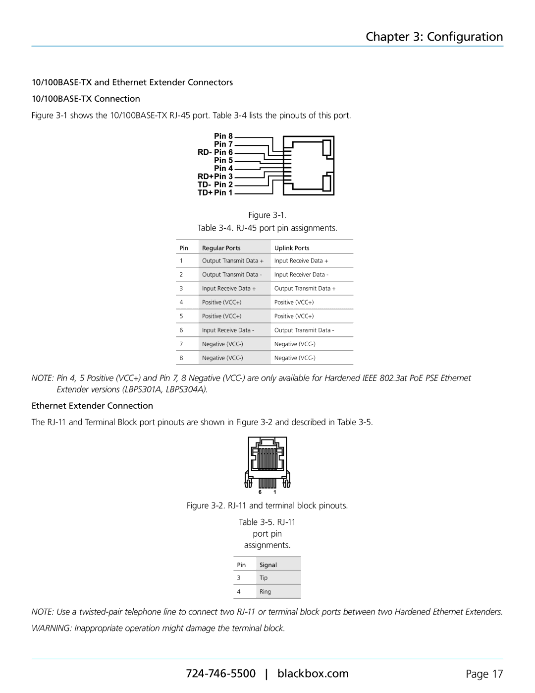
Figure 3-1 shows the 10/100BASE-TX RJ-45 port. Table 3-4 lists the pinouts of this port.
Figure
Table 3-4. RJ-45 port pin assignments.
Pin | Regular Ports | Uplink Ports |
|
|
|
1 | Output Transmit Data + | Input Receive Data + |
|
|
|
2 | Output Transmit Data - | Input Receiver Data - |
|
|
|
3 | Input Receive Data + | Output Transmit Data + |
|
|
|
4 | Positive (VCC+) | Positive (VCC+) |
|
|
|
5 | Positive (VCC+) | Positive (VCC+) |
|
|
|
6 | Input Receive Data - | Output Transmit Data - |
|
|
|
7 | Negative | Negative |
|
|
|
8 | Negative | Negative |
|
|
|
NOTE: Pin 4, 5 Positive (VCC+) and Pin 7, 8 Negative
Ethernet Extender Connection
The
Figure 3-2. RJ-11 and terminal block pinouts.
Table
port pin
assignments.
Pin Signal
3Tip
4Ring
NOTE: Use a
WARNING: Inappropriate operation might damage the terminal block.
Page 17 |