CHAPTER 3 Installing the Switch
Connecting Switches in a Stack
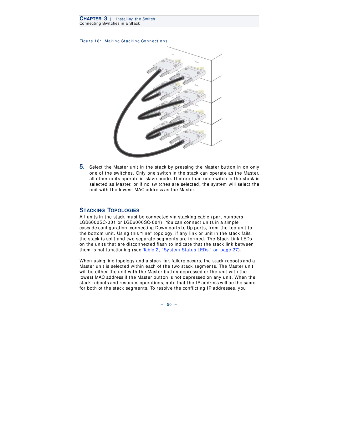
Figure 18: Making Stacking Connections
5.Select the Master unit in the stack by pressing the Master button in on only one of the switches. Only one switch in the stack can operate as the Master, all other units operate in slave mode. If more than one switch in the stack is selected as Master, or if no switches are selected, the system will select the unit with the lowest MAC address as the Master.
STACKING TOPOLOGIES
All units in the stack must be connected via stacking cable (part numbers
When using line topology and a stack link failure occurs, the stack reboots and a Master unit is selected within each of the two stack segments. The Master unit will be either the unit with the Master button depressed or the unit with the lowest MAC address if the Master button is not depressed on any unit. When the stack reboots and resumes operations, note that the IP address will be the same for both of the stack segments. To resolve the conflicting IP addresses, you
– 50 –