ServSwitch Wizard DVI/USB SRX
3.2 Connections
Installation of the ServSwitch Wizard DVI/USB SRX modules is straightforward and requires minimal configuration in most cases.
•Connections at the local module
•Connections at the remote module
Note: After all connections are made, power up the monitor connected to the remote module, then power up the remote mod- ule and finally switch on the computer connected to the local module.
3.2.1 Connections at the local module 3.2.1.1 Video connections
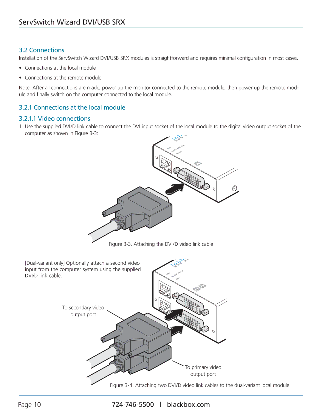
1 Use the supplied DVI/D link cable to connect the DVI input socket of the local module to the digital video output socket of the
computer as shown in Figure
E R
D | S |
| |
R | |
B
|
|
| TO |
ON |
| R | |
EMO |
| ||
| TE | LIN | |
|
| K |
|
Figure 3-3. Attaching the DVI/D video link cable
[Dual-variant only] Optionally attach a second video input from the computer system using the supplied DVI/D link cable.
|
| D | N | S |
| E |
|
| |
|
|
|
| |
R |
|
|
| |
|
|
| TO |
|
ON |
| R |
| |
EMO |
|
| ||
| TE | LINK |
| |
|
|
| ||
B
A
To secondary video
output port
To primary video
output port
Figure 3-4. Attaching two DVI/D video link cables to the dual-variant local module
Page 10 |