Chapter 4: Operation
3.2.2.6 Power connections
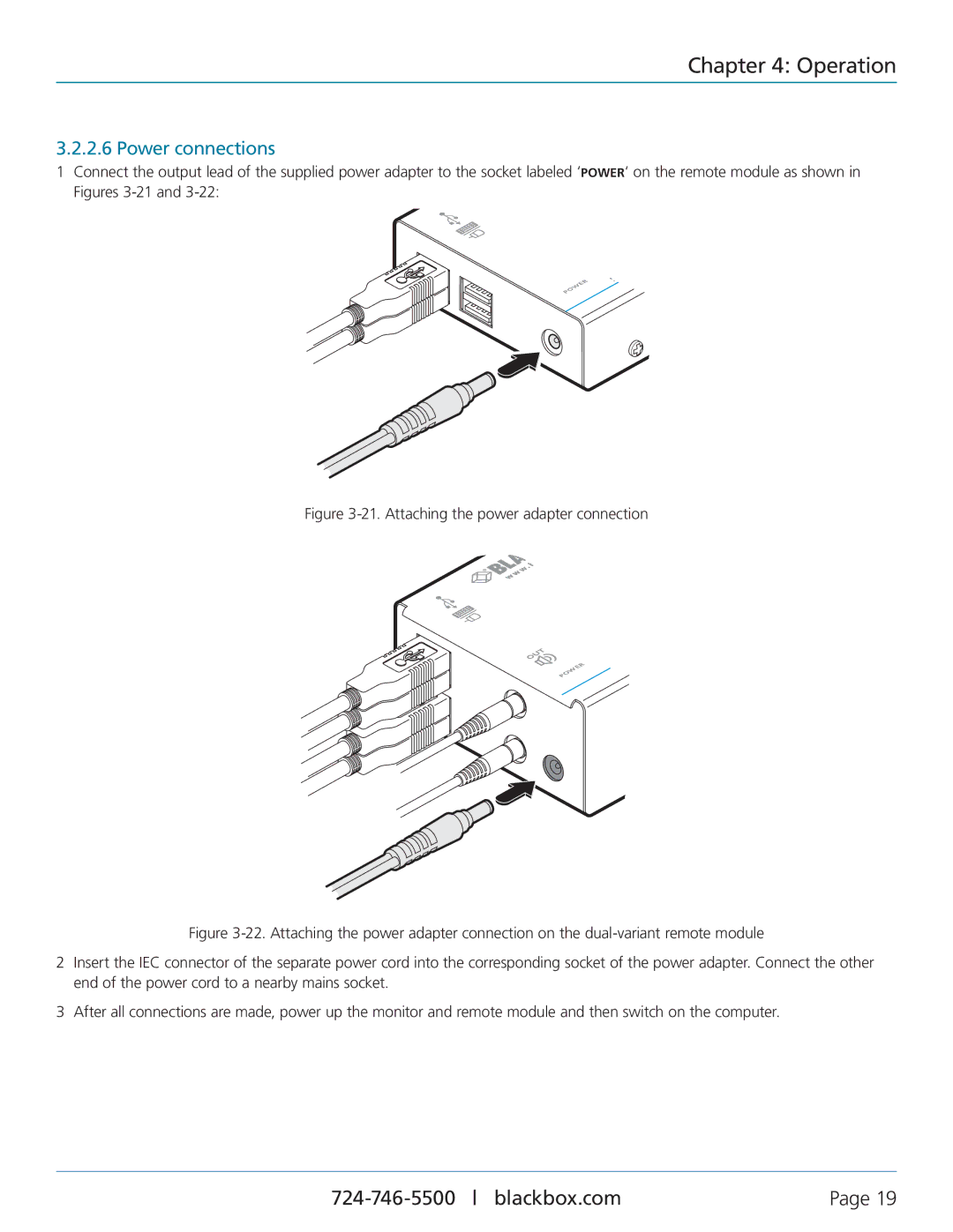
1Connect the output lead of the supplied power adapter to the socket labeled ‘POWER‘ on the remote module as shown in Figures
WER PO
| w |
S | |
v | B |
r |
|
e |
|
S |
|
Figure 3-21. Attaching the power adapter connection
REMO
OUT
R
WE
PO
v r e S
Figure 3-22. Attaching the power adapter connection on the dual-variant remote module
2Insert the IEC connector of the separate power cord into the corresponding socket of the power adapter. Connect the other end of the power cord to a nearby mains socket.
3After all connections are made, power up the monitor and remote module and then switch on the computer.
Page 19 |