ServSwitch Wizard DVI/USB SRX
3.2.1.6 Power connections (optional)
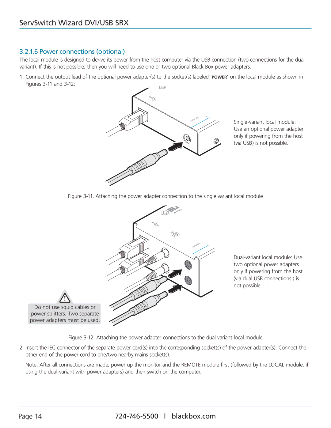
The local module is designed to derive its power from the host computer via the USB connection (two connections for the dual variant). If this is not possible, then you will need to use one or two optional Black Box power adapters.
1Connect the output lead of the optional power adapter(s) to the socket(s) labeled ‘POWER‘ on the local module as shown in Figures
WER PO
| w |
S | |
v | B |
r |
|
e |
|
S |
|
Figure 3-11. Attaching the power adapter connection to the single variant local module
LOCA
IN
WER
PO
Do not use squid cables or
power splitters. Two separate power adapters must be used.
r e S
Figure 3-12. Attaching the power adapter connections to the dual variant local module
2Insert the IEC connector of the separate power cord(s) into the corresponding socket(s) of the power adapter(s). Connect the other end of the power cord to one/two nearby mains socket(s).
Note: After all connections are made, power up the monitor and the REMOTE module first (followed by the LOCAL module, if using the
Page 14 |