. A complete Parts List is available at www.MillerWelds.com
SECTION 7 − OPERATING AUXILIARY EQUIPMENT
| |||||
|
|
|
| ! | If unit does not have GFCI re- |
|
|
|
|
| ceptacles, use |
|
| 4 |
|
| extension cord. |
|
|
| NOTICE − Disconnect equipment | ||
1 |
|
|
| ||
| 2 |
|
| from auxiliary power receptacles dur- | |
|
|
|
| ing start−up and shutdown. Some | |
|
|
|
| equipment can be damaged by | |
|
|
|
| changes in frequency as engine rpms | |
|
|
|
| change during | |
|
|
|
| down. | |
|
|
|
| . Weld output and 60 Hz generator | |
|
|
|
|
| power output at receptacles RC1 |
|
|
|
|
| and RC2 are not always available |
|
|
|
|
| at the same time. When welding, |
|
|
|
|
| generator power is available from |
|
| See Section |
| AC receptacle RC3 only (see | |
|
|
| Section | ||
|
|
| |||
|
|
|
| ||
|
| information. | . Generator power is available at | ||
|
|
|
|
| receptacles RC1 and RC2 only at |
|
|
|
|
| 1800 rpm. If generator is not |
|
|
|
|
| locked at 1800 rpm, engine |
|
|
|
|
| speed increases in response to |
|
|
|
|
| weld load and generator power |
|
|
|
|
| output stops at receptacles RC1 |
|
|
|
|
| and RC2. Generator power load |
|
|
|
|
| does not affect engine speed. |
|
|
|
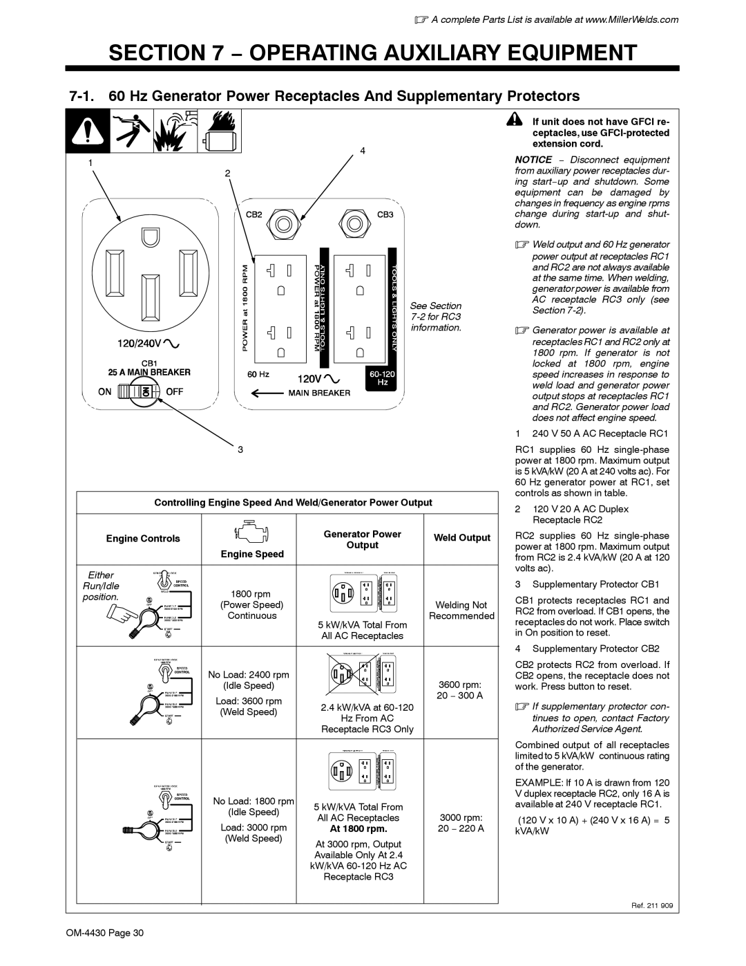
| 1 | 240 V 50 A AC Receptacle RC1 |
| 3 |
|
| RC1 supplies 60 Hz | |
|
|
|
| power at 1800 rpm. Maximum output | |
|
|
|
| is 5 kVA/kW (20 A at 240 volts ac). For | |
|
|
|
| 60 Hz generator power at RC1, set | |
| Controlling Engine Speed And Weld/Generator Power Output | controls as shown in table. | |||
| 2 | 120 V 20 A AC Duplex | |||
|
|
|
| ||
|
|
|
|
| Receptacle RC2 |
Engine Controls | Generator Power | Weld Output | RC2 supplies 60 Hz | ||
| Engine Speed | Output |
| power at 1800 rpm. Maximum output | |
|
|
| from RC2 is 2.4 kVA/kW (20 A at 120 | ||
Either |
|
|
| volts ac). | |
|
|
| 3 | Supplementary Protector CB1 | |
Run/Idle | 1800 rpm |
|
| ||
position. |
|
| CB1 protects receptacles RC1 and | ||
| (Power Speed) |
| Welding Not | ||
|
| RC2 from overload. If CB1 opens, the | |||
| Continuous |
| Recommended | ||
| 5 kW/kVA Total From | receptacles do not work. Place switch | |||
|
|
| |||
|
| All AC Receptacles |
| in On position to reset. | |
|
|
|
|
| |
|
|
|
| 4 | Supplementary Protector CB2 |
| No Load: 2400 rpm |
|
| CB2 protects RC2 from overload. If | |
|
| 3600 rpm: | CB2 opens, the receptacle does not | ||
| (Idle Speed) |
| work. Press button to reset. | ||
| Load: 3600 rpm |
| 20 − 300 A | . If supplementary protector con- | |
| 2.4 kW/kVA at |
| |||
| (Weld Speed) |
| |||
| Hz From AC |
|
| tinues to open, contact Factory | |
|
|
|
| ||
|
| Receptacle RC3 Only |
|
| Authorized Service Agent. |
|
|
|
| Combined output of all receptacles | |
|
|
|
| limited to 5 kVA/kW continuous rating | |
|
|
|
| of the generator. | |
|
|
|
| EXAMPLE: If 10 A is drawn from 120 | |
| No Load: 1800 rpm |
|
| V duplex receptacle RC2, only 16 A is | |
| 5 kW/kVA Total From |
| available at 240 V receptacle RC1. | ||
| (Idle Speed) | All AC Receptacles | 3000 rpm: | (120 V x 10 A) + (240 V x 16 A) = 5 | |
| Load: 3000 rpm | ||||
| At 1800 rpm. | 20 − 220 A | kVA/kW | ||
| (Weld Speed) | At 3000 rpm, Output |
|
|
|
|
|
|
|
| |
|
| Available Only At 2.4 |
|
|
|
|
| kW/kVA |
|
|
|
|
| Receptacle RC3 |
|
|
|
|
|
|
|
| Ref. 211 909 |
|
|
|
|
| |
