Miller LegendR302
OM-4430217 243R
Processes
Description
From Miller to You
SECTION 1 − SAFETY PRECAUTIONS − READ BEFORE USING
TABLE OF CONTENTS
SECTION 2 − CONSIGNES DE SÉCURITÉ − LIRE AVANT UTILISATION
TABLE OF CONTENTS
SECTION 11 − GENERATOR POWER GUIDELINES
OPTIONS AND ACCESSORIES
WARRANTY
1-1. Symbol Usage
1-2. Arc Welding Hazards
SECTION 1 − SAFETY PRECAUTIONS − READ BEFORE USING
NOTICE − Indicates statements not related to personal injury
FUMES AND GASES can be hazardous
BUILDUP OF GAS can injure or kill
ARC RAYS can burn eyes and skin
WELDING can cause fire or explosion
1-3. Engine Hazards
1-4. Compressed Air Hazards
BATTERY ACID can BURN SKIN and EYES
TRAPPED AIR PRESSURE AND WHIPPING HOSES can cause injury
1-5. Additional Symbols For Installation, Operation, And Maintenance
1-7. Principal Safety Standards
1-6. California Proposition 65 Warnings
1-8. EMF Information
For Gasoline Engines
2-1. Signification des symboles
SECTION 2 − CONSIGNES DE SÉCURITÉ − LIRE AVANT UTILISATION
2-2. Dangers relatifs au soudage à l’arc
Indique des instructions spécifiques
DES PIÈCES CHAUDES peuvent provoquer des brûlures graves
2-3. Dangers existant en relation avec le moteur
2-4. Dangers liés à l’air comprimé
D Affûter l’électrode au tungstène uniquement à la meuleuse dotée de protecteurs. Cette manœuv- re est à exécuter dans un endroit sûr lorsque l’on porte l’équipement homologué de protection du visage, des mains et du corps
2-6. Proposition californienne 65 Avertissements
2-7. Principales normes de sécurité
2-8. Information EMF
Pour les moteurs à essence
SECTION 3 − DEFINITIONS
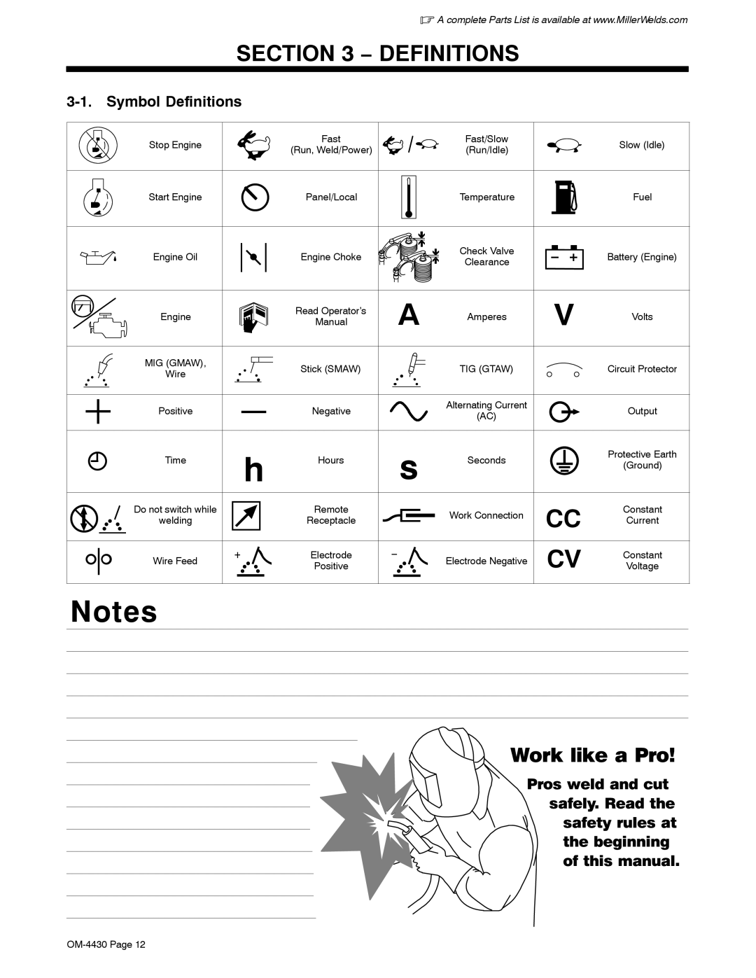
3-1. Symbol Definitions
Work like a Pro
SECTION 4 − SPECIFICATIONS
4-2. Weld, Power, And Engine Specifications
4-3. Dimensions, Weights, and Operating Angles
4-1. Description
4-4. Dimensions For Units With Optional Running Gear
4-5. Fuel Consumption While Welding And Using Generator Power
4-6. Generator Power Curve
WELD POSITION FLAT
HORIZONTAL
VERTICAL
4-7. Duty Cycle
4-8. TIG Mode Volt-Ampere Curves
Continuous Welding
A. CC/DC Stick Mode
4-9. Stick And MIG Mode Volt-Ampere Curves
B. CV/DC MIG Mode
SECTION 5 − INSTALLATION
5-1. Installing Welding Generator
vehicle frame. Always connect a ground wire
Movement Do not lift unit from end
5-2. Engine Prestart Checks
Follow run-in procedure in engine
Keep battery in good condition
Store battery in warm area
5-3. Connecting Or Replacing The Battery
Replacing The Battery
Remove end panel to replace battery
Connect negative − cable last
Work like a Pro
5-4. Installing Exhaust Pipe
Stop engine and let cool
5-5. Connecting To Weld Output Terminals
Stop engine
Failure to properly connect
damage your machine
5-6. Selecting Weld Cable Sizes
5-7. Remote Receptacle Information
6-1. Front Panel Controls
SECTION 6 − OPERATING WELDING GENERATOR
For maximum weld output above
6-2. Description Of Engine Controls See Section
6-3. Cold Weather Engine Operation
Engine Control Switch
Generator power is available at recep
6-4. Controlling Engine Speed And Weld/Generator Output
Generator Power Output
Engine Controls
Either Run/Idle position
6-5. Process Switch
Wire Position
The unit will not return to idle speed
Stick Positions
6-6. Stick Start Procedure − Scratch Start Technique
6-7. TIG Lift-Arc Start Procedure
Lift-Arc t TIG
Application
6-8. Remote Voltage/Amperage Control
Max 160 A DC
7-1. 60 Hz Generator Power Receptacles And Supplementary Protectors
SECTION 7 − OPERATING AUXILIARY EQUIPMENT
Generator power is available at
weld load and generator power
7-2. Variable Frequency Hz Generator Power Receptacle RC3
Press button to reset. If supple
rized Service Agent
Work like a Pro
Each 120 V Duplex
Receptacle
Current Available in Amperes
Receptacle
SECTION 8 − MAINTENANCE & TROUBLESHOOTING
8-1. Routine Maintenance
for important start-up, service, and storage
information. Service engine more often if
8-2. Maintenance Label
OM-4430 Page
8-4. Servicing Air Cleaner
8-3. Servicing Optional Spark Arrestor
Stop engine and let cool
Stop engine
Stop engine and let cool
8-5. Changing Engine Oil, Oil Filter, And Fuel Filter
Stop engine, tighten connec- tions as necessary, and wipe up fuel
Stop engine
8-6. Overload Protection
803 773−A / Ref. 216 172-D
8-7. Troubleshooting
A. Welding
Trouble
Remedy
Trouble
Remedy
Trouble
Remedy
Trouble
D. Engine
Remedy
SECTION 9 − PARTS LIST
9-1. Recommended Spare Parts
SECTION 10 − ELECTRICAL DIAGRAMS
Figure 10-1. Circuit Diagram For Welding Generator Models
OM-4430 Page
232 961-A
SECTION 11 − GENERATOR POWER GUIDELINES
11-1. Selecting Equipment
11-2. Grounding Generator To Truck Or Trailer Frame
Be sure equipment has double insulated symbol and/or word- ing on it
11-3. Grounding When Supplying Building Systems
11-4. How Much Power Does Equipment Require?
Use ground device as stated in electrical codes
Amperes x Volts = Watts
11-5. Approximate Power Requirements For Industrial Motors
11-6. Approximate Power Requirements For Farm/Home Equipment
Industrial Motors
Rating
11-7. Approximate Power Requirements For Contractor Equipment
Contractor
Rating
Starting Watts
11-8. Power Required To Start Motor
11-9. How Much Power Can Generator Supply?
Single-Phase Induction Motor Starting Requirements
Motor Start
11-10. Typical Connections To Supply Standby Power
Customer-supplied equipment
11-11. Selecting Extension Cord Use Shortest Cord Possible
Cord Lengths for 120 Volt Loads
Maximum Allowable Cord Length in ft m for Conductor Size AWG
Current
SOCKET/WRENCH SELECTION TABLE
U.S. STANDARD
METRIC
Welding Symbols
Ref. AWS/ANSI A2.4
Page
Page
Warranty Questions?
Service
Call 1-800-4-A-MILLER for your local Miller distributor
Support
For Service
Owner’s Record
Contact a DISTRIBUTOR or SERVICE AGENCY near you
Please complete and retain with your personal records